
Operating Environment & Safety Compliance
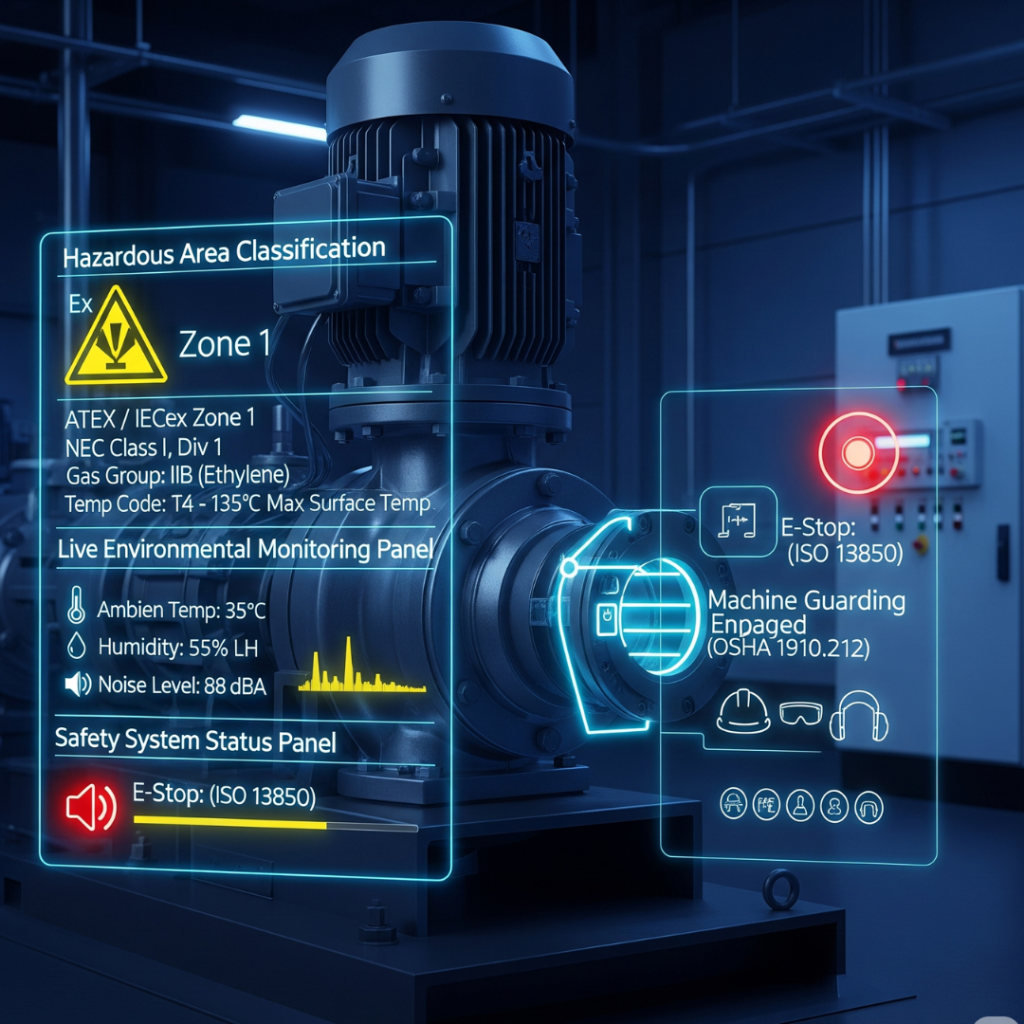
Overview of Operating Environment & Safety Specifications
| Specification | Brief Definition |
| Indoor / Outdoor Installation | Defines whether equipment will be installed inside a building (indoor) or exposed to external weather conditions (outdoor), determining the required robustness. |
| Ambient Temperature Range | The minimum and maximum temperature of the surrounding air in which the equipment is designed to function safely and effectively. |
| Ambient Humidity Range & Condensation Risk | The amount of water vapor in the air, expressed as Relative Humidity (RH), and the likelihood of this vapor turning into liquid on equipment surfaces. |
| Operating Altitude | The elevation above sea level at which the equipment will be installed and operated, affecting air density, pressure, and cooling effectiveness. |
| Ingress Protection (IP) or NEMA Rating | Defines the degree of sealing effectiveness of an electrical enclosure against intrusion from foreign objects (solids) and moisture (liquids). |
| Presence of Airborne Dust/Particulates | Identifies the presence and nature of solid particles suspended in the air, which can range from inert nuisance dusts to hazardous combustible or conductive dusts. |
| Ingress of Foreign Material (FME/FOD) Prevention | A set of stringent controls and design principles to prevent extraneous material (tools, fasteners, debris) from entering and compromising a critical system. |
| Secondary & Spill Containment Requirements | A backup system designed to capture and hold leaks or spills from a primary container to prevent hazardous materials from escaping into the environment. |
| Fugitive Emissions Monitoring | Unintentional leaks of gases or vapors from pressurized industrial equipment, such as valves, pipe connections, pumps, and compressors. |
| Exposure to Corrosive Atmospheres | An environment containing chemical agents (e.g., industrial pollutants, salt spray) that can degrade or destroy materials through chemical reactions. |
| UV Exposure Conditions | The equipment’s exposure to ultraviolet (UV) radiation from sunlight, which causes photooxidative degradation in organic materials like plastics and rubbers. |
| Flood Plain / Maximum Flood Level | Applies to equipment in a low-lying area subject to flooding, dictating requirements for elevation, anchoring, and flood-proofing. |
| Ventilation Requirements | The process of supplying or removing air to control air quality, temperature, and humidity within a space or equipment enclosure. |
| Machine Guarding Requirements | The use of physical barriers, devices, or procedures to protect personnel from hazards created by moving machine parts. |
| Emergency Stop (E-Stop) Functionality | A control function, initiated by a single human action, designed to avert or reduce an existing hazard to people, machinery, or work in progress. |
| Lockout/Tagout (LOTO) Provisions | A safety procedure to ensure dangerous machines are properly shut off and not able to be started up prior to the completion of maintenance or servicing work. |
| Hazardous Area Classification System | A formal process to identify and classify areas where flammable gases, vapors, or combustible dusts may exist in quantities sufficient to cause a fire or explosion. |
| Gas Groups | The categorization of flammable gases and vapors based on their physical properties and volatility to simplify the selection of explosion-proof equipment. |
| Dust Groups | The categorization of combustible dusts based on their properties, specifically their conductivity and ignitability. |
| Temperature Code (T-Code) | Indicates the maximum surface temperature that any part of the equipment can reach, ensuring it is lower than the auto-ignition temperature of the hazardous atmosphere. |
| Equipment Protection Level (EPL) | A level of protection assigned to equipment based on its likelihood of becoming an ignition source, correlating its safety level to the Zone in which it can be used. |
| Explosion Protection Method | The specific design and construction technique (e.g., Flameproof, Intrinsic Safety) used to prevent equipment from igniting an explosive atmosphere. |
| Combustible Dust Hazard Control | A holistic approach combining equipment design, facility management, and protective systems to prevent and mitigate dust explosions. |
| Regulatory Compliance & Risk Assessment | The process of ensuring adherence to applicable laws and standards, and the systematic process of identifying, evaluating, and controlling workplace risks. |
| CE Marking (Machinery Directive) | A mandatory conformity marking for products sold within the European Economic Area (EEA), indicating they meet essential health and safety requirements. |
| Material Flammability Rating (UL 94) | A plastics flammability standard from Underwriters Laboratories (UL) that classifies plastic materials based on how they burn in a controlled test. |
| Potable Water / NSF Compliance | Requires that equipment in contact with drinking water must not introduce harmful contaminants, demonstrated through certification to NSF International standards. |
| Hygienic Design Standards | Design principles for equipment in the food, beverage, and pharmaceutical industries to make them easily and reliably cleanable to a microbiological level. |
| Biocompatibility Requirements (Medical/Pharma) | The ability of a material or device to perform its function in contact with the human body or biological systems without an adverse biological response. |
| Clean-in-Place / Steam-Out (CIP/SIP) Conditions | Defines the equipment’s ability to withstand automated cleaning with aggressive chemicals (CIP) and sterilization with high-temperature steam (SIP). |
| Electrical Grounding and Bonding | Grounding connects an electrical system to the earth for overvoltage protection; Bonding connects all metallic parts together to create a safe path for fault current. |
Part 1: Foundational Operating Environment Parameters
The initial phase of any equipment specification process involves defining the fundamental physical environment in which the equipment will operate. These parameters are the most critical, as a misjudgment at this stage will compromise all subsequent design and configuration choices. The primary determination is whether the equipment will be sheltered from or exposed to the elements, which then dictates the required resilience to atmospheric conditions such as temperature, humidity, and altitude.
Definition
This specification defines whether the equipment will be installed inside a building or facility (indoor) or exposed to external weather conditions (outdoor). This is the primary determinant for the required robustness of the equipment’s enclosure and external components.
Classifications
Indoor: Equipment is protected from weather elements like rain, snow, and direct sunlight. The environment may be climate-controlled (e.g., an office or lab) or non-climate-controlled (e.g., a factory floor or warehouse).
Outdoor: Equipment is exposed to all environmental conditions, including direct sunlight, rain, wind, snow, and extreme temperature fluctuations. It may be fully exposed or partially sheltered (e.g., under an awning).
Examples
An indoor installation could be a control panel for a manufacturing line inside a factory or a pump located in a climate-controlled mechanical room.
An outdoor installation could be a transformer in a utility substation, an air compressor on a construction site, or a security camera mounted on the exterior of a building.
Advanced Knowledge
The distinction between “indoor” and “outdoor” is not absolute but represents a spectrum of environmental hostility. A non-climate-controlled indoor location, such as a steel mill or a wet-processing area in a food plant, can present conditions (high heat, humidity, corrosive agents) that are more severe than a sheltered outdoor location in a mild climate. Therefore, a Sales Engineer must probe beyond the simple “indoor” or “outdoor” label. Key follow-up questions include: “Is the indoor location climate-controlled?”, “Are there significant nearby sources of heat or moisture?”, and “Will the outdoor equipment have any overhead protection?”. Answering these questions clarifies the true environmental challenge and prevents the misapplication of an under-protected indoor-rated unit in a harsh “indoor” environment.
Technical Impact on Equipment
This is the most fundamental specification for an enclosure.
Material Selection: Outdoor equipment requires materials with high weather and corrosion resistance, such as thick-gauge stainless steel, aluminum, or fiberglass-reinforced polyester. Indoor equipment can often use less robust materials like thinner-gauge steel or heavy-duty plastics.
Construction & Sealing: Outdoor enclosures must be robustly constructed with gaskets and seals to prevent ingress of water and dust, often requiring higher Ingress Protection (IP) or NEMA ratings. Indoor enclosures may be vented and are subject to less stringent sealing requirements.
Security: Outdoor equipment, often located in isolated areas, may require enhanced security features like reinforced locking mechanisms and alarms, which are typically unnecessary for indoor units in secure facilities.
Regulatory Compliance: Standards bodies like OSHA have specific rules for outdoor electrical installations, such as requiring that exposed live parts are accessible only to qualified personnel.
Definition
Ambient temperature is the temperature of the surrounding air in the immediate vicinity of the equipment. The operating ambient temperature range specifies the minimum and maximum temperatures at which the equipment is designed to function safely and effectively.
Common Units
Degrees Celsius (∘C)
Degrees Fahrenheit (∘F)
Common Unit Conversions
∘C=(∘F−32)×5/9
∘F=(∘C×9/5)+32
Examples
A commercial-grade electronic device might have an operating range of 0 °C to 70 °C.
Industrial-grade equipment is typically rated for a wider range, such as -40 °C to 85 °C, to withstand more extreme conditions.
In hot and humid regions of Asia, such as Malaysia, average outdoor temperatures can range from 23.7 °C to 31.3 °C, with peaks being much higher, demanding equipment designed for these conditions.
Advanced Knowledge
The stated “maximum ambient temperature” provided by a client can be misleading if considered in isolation. The true thermal load on a piece of equipment is a combination of the ambient air temperature, solar radiation (solar load), and radiant heat from nearby machinery. For example, a dark-colored enclosure installed in direct sunlight on a black rooftop will experience a surface temperature far higher than the recorded air temperature. Similarly, equipment placed near furnaces, compressors, or engines will be subjected to a higher local ambient temperature than the rest of the facility. An expert Sales Engineer must inquire about these additional factors—”Will the unit be in direct sunlight?” and “What heat-generating equipment will be nearby?”—to accurately calculate the total heat load and specify an adequate thermal management system (e.g., cooling fans, air conditioners).
Technical Impact on Equipment
Operating outside the specified temperature range has severe consequences for equipment performance and longevity.
High Temperatures: Can cause electronic components to overheat, leading to malfunctions, automatic shutdowns, or permanent damage. High temperatures accelerate the aging of materials, reducing the lifespan of components like processors, power supplies, and insulation.
Low Temperatures: Can cause mechanical parts to become brittle and fail. Lubricants can thicken, leading to startup problems in motors and bearings. Condensation can form on components as they warm up, creating a risk of short circuits and corrosion.
Component Selection: Components must be selected based on their temperature grade (e.g., Commercial, Industrial, Military) to ensure they are suitable for the application’s expected temperature range.
Thermal Management: The maximum ambient temperature is a critical input for sizing cooling systems like fans, heat exchangers, or air conditioners. An underestimated thermal load will lead to an undersized cooling system and subsequent equipment failure.
Definition
Ambient humidity refers to the amount of water vapor in the air, typically expressed as Relative Humidity (RH). RH is the ratio of the current amount of water vapor in the air to the maximum amount it could hold at that temperature. Condensation risk is the likelihood of this water vapor turning into liquid water on equipment surfaces, which occurs when a surface’s temperature drops to or below the “dew point”.
Common Units
Relative Humidity (RH), expressed as a percentage (%).
Examples
A data center requires a strictly controlled humidity range, often 45-55% RH, to prevent both static discharge (too low) and corrosion (too high).
In tropical Southeast Asia, outdoor humidity can consistently be above 80% RH, creating a significant condensation risk for outdoor equipment.
A standard office environment is typically maintained between 30% and 60% RH for human comfort and equipment safety.
Advanced Knowledge
Condensation is not just an environmental issue; it is closely tied to the equipment’s operational cycle. During continuous operation, the waste heat generated by internal components often keeps the enclosure’s interior surfaces above the ambient dew point, preventing condensation even in a humid environment. The period of greatest risk is often during equipment downtime, such as overnight or on weekends. As the equipment cools to the lower nighttime ambient temperature, the humid air trapped inside the enclosure from daytime operation will cool as well. When the internal surfaces reach the dew point, condensation forms directly on sensitive electronics and mechanical parts. This moisture can cause short circuits on startup and long-term corrosion. Therefore, for equipment that operates intermittently in high-humidity regions, a Sales Engineer must assess the operating cycle. If not 24/7, specifying an anti-condensation heater controlled by a thermostat or humidistat becomes a critical requirement to protect the equipment during its vulnerable offline periods.
Technical Impact on Equipment
Both high and low humidity levels pose significant risks to industrial equipment.
High Humidity (>60% RH): Promotes corrosion of metallic components, leading to premature failure. It can cause condensation, which can lead to electrical short circuits, arcing, and complete system failure. High humidity also supports the growth of mold and mildew, which can degrade materials and pose health risks.
Low Humidity (<40% RH): Increases the risk of electrostatic discharge (ESD), which can damage or destroy sensitive electronic components like microchips and circuit boards. Dry air can also cause materials like gaskets and seals to become brittle and crack.
Condensation Prevention: For equipment in environments with high humidity and fluctuating temperatures, specific design features are required. These can include ventilation to equalize temperature, dehumidifiers to remove moisture, or anti-condensation heaters to keep the internal temperature above the dew point. The choice of method depends on the severity of the conditions and the equipment’s operating cycle.
Definition
Operating altitude is the elevation above sea level at which the equipment will be installed and operated. As altitude increases, the air becomes less dense (thinner) and atmospheric pressure decreases.
Common Units
Meters (m)
Feet (ft)
Common Unit Conversions
1 m = 3.281 ft
1 ft = 0.3048 m
Examples
Most standard industrial equipment is rated for operation up to 1,000 m (approx. 3,300 ft) without any adjustment.
A mining operation in the Andes mountains in Peru might be located at 4,800 m (approx. 15,750 ft), requiring specially designed or significantly derated equipment.
A generator operating at 6,000 ft would need to be derated; for example, a 50 HP motor might only be able to safely produce 47 HP.
Advanced Knowledge
The impact of altitude is a multi-faceted engineering challenge that affects mechanical, thermal, and electrical systems in distinct ways. A client may only be aware of one aspect, such as the power loss in a diesel engine. However, the lower air density at altitude creates three separate problems:
Mechanical (Combustion): Internal combustion engines lose power because there is less oxygen available per unit volume of air for combustion. A naturally aspirated engine can lose 3% of its power for every 1,000 ft of elevation gain.
Thermal (Cooling): The thinner air is less effective at transferring heat away from surfaces. This reduces the efficiency of fans, heat sinks, and radiators, meaning equipment runs hotter and is more prone to overheating.
Electrical (Insulation): The dielectric strength of air (its ability to act as an insulator) decreases at higher altitudes. This increases the risk of arcing or “flashover” between electrical conductors. Equipment may require greater physical spacing between high-voltage components to operate safely. A key advantage for battery-electric equipment is its immunity to the oxygen-availability problem, allowing it to maintain consistent power and torque at high altitudes where diesel engines struggle. This provides a significant technical and performance benefit in mountainous regions.
Technical Impact on Equipment
Altitude significantly affects equipment performance and requires a process known as derating, which is the intentional reduction of a performance metric (like power or voltage) to ensure safe operation under non-standard conditions.
Engine Derating: Internal combustion engines must be derated for power output to compensate for the lack of oxygen. Turbocharged engines perform better than naturally aspirated ones but still experience power loss.
Thermal Derating: Cooling systems may need to be oversized (e.g., larger fans, more powerful blowers, bigger radiators) to achieve the same level of heat dissipation as at sea level. The operating current of components like soft starters and vacuum contactors may need to be derated because they will run hotter.
Electrical Derating: The maximum allowable operating voltage (dielectric withstand) of electrical equipment must be derated above a certain altitude (typically 2,000 m) to prevent electrical arcing. This is critical for switchgear, contactors, and circuit breakers.
Part 2: Contamination, Ingress, and Containment
After defining the ambient operating environment, the next critical step is to specify the integrity of the boundary between the equipment’s internal components and that external environment. This involves protecting the equipment from physical contaminants like dust and water, preventing the equipment from releasing contaminants into the environment, and ensuring that foreign objects do not compromise sensitive processes.
Definition
This specification defines the degree of sealing effectiveness of an electrical enclosure against intrusion from foreign objects (solids like dust and dirt) and moisture (liquids like water). Two primary standards are used globally:
IP (Ingress Protection) Rating: An international standard (IEC 60529) that uses a two-digit code. The first digit represents protection against solids, and the second digit represents protection against liquids.
NEMA (National Electrical Manufacturers Association) Rating: A North American standard (NEMA 250) that defines enclosure types. NEMA ratings cover protection against ingress of solids and liquids but also include additional criteria such as corrosion resistance and performance in hazardous locations or under icing conditions.
Classifications
The two systems are not directly equivalent, as NEMA includes broader criteria. However, a comparison can be made for ingress protection purposes. A higher number generally indicates a higher level of protection.
- Table 1: IP Ratings Explained
| First Digit | Protection Against Solids | Second Digit | Protection Against Liquids |
| 0 | No protection. | 0 | No protection. |
| 1 | Objects >50 mm (e.g., accidental hand contact). | 1 | Dripping water (vertically falling drops). |
| 2 | Objects >12.5 mm (e.g., fingers). | 2 | Dripping water when tilted up to 15°. |
| 3 | Objects >2.5 mm (e.g., tools, thick wires). | 3 | Spraying water (up to 60° from vertical). |
| 4 | Objects >1 mm (e.g., most wires, screws). | 4 | Splashing water from any direction. |
| 5 | Dust protected (limited ingress permitted, no harmful deposit). | 5 | Water jets from a nozzle (6.3 mm) from any direction. |
| 6 | Dust tight (no ingress of dust). | 6 | Powerful water jets from a nozzle (12.5 mm) from any direction. |
| 7 | Temporary immersion in water (up to 1 m for 30 min). | ||
| 8 | Continuous immersion in water (depth specified by manufacturer). | ||
| 9K | Powerful, high-temperature water jets (close-range steam cleaning). |
- Table 2: Common NEMA Ratings and Approximate IP Equivalents
| NEMA Rating | Description | Approximate IP Equivalent |
| 1 | Indoor, general purpose, protects against falling dirt. | IP20 |
| 3R | Weather-resistant (rain, sleet, snow), undamaged by ice. | IP24 |
| 4 | Watertight (hose-directed water), dust-tight, undamaged by ice. | IP66 |
| 4X | Watertight, dust-tight, corrosion-resistant. | IP66 |
| 6 | Submersible (temporary, limited depth). | IP67 |
| 6P | Submersible (prolonged, specified depth). | IP68 |
| 12 | Indoor, protects against dripping liquids, falling dirt, circulating dust. | IP54 |
Examples
An indoor control panel in a clean, dry room might only require a NEMA 1 or IP20 rating.
Equipment on a food processing floor that is regularly washed down with high-pressure hoses would require a NEMA 4X or IP66 rating. The “X” in NEMA 4X is critical as it denotes resistance to corrosive cleaning agents.
A sensor submerged in a water tank would need a NEMA 6P or IP68 rating.
Advanced Knowledge
While clients in Asia may specify an IP rating as it is the international standard, a Sales Engineer can demonstrate superior technical expertise by understanding the additional protections offered by the NEMA system. For instance, in coastal regions or chemical plants, corrosion is a primary cause of equipment failure. A client might request an “IP66” enclosure. While technically correct for sealing, this specification alone does not address material degradation from a saline or chemical atmosphere. Recommending a NEMA 4X-rated enclosure provides the required IP66 level of sealing plus guaranteed corrosion resistance, offering a more robust and reliable long-term solution. This elevates the conversation from meeting a basic specification to providing a comprehensive solution engineered for the full scope of environmental challenges.
Technical Impact on Equipment
The IP or NEMA rating is a fundamental design choice that dictates the enclosure’s construction, materials, and cost.
Design and Manufacturing: Achieving higher ratings requires more complex designs with gasketing, sealed connectors, and more robust construction, which increases manufacturing costs.
Reliability: Selecting the correct rating is critical for the equipment’s operational life. An underrated enclosure will allow contaminants to enter, causing corrosion, short circuits, and premature failure.
Application Suitability: The rating determines where the equipment can be safely installed. An IP54/NEMA 12 enclosure is suitable for general indoor industrial use but would fail quickly if installed outdoors without protection.
Definition
This specification identifies the presence and nature of solid particles suspended in the air. These can range from inert nuisance dusts to hazardous materials, including combustible or conductive dusts, which pose significant safety risks.
Applicable Standards
OSHA Permissible Exposure Limits (PELs): Legally enforceable limits on the concentration of hazardous substances, including various dusts, in workplace air (e.g., 29 CFR 1910.1000).
NFPA Standards for Combustible Dust: A series of standards (e.g., NFPA 652, 484) that provide requirements for managing combustible dust hazards to prevent explosions.
Particulate Matter (PM2.5, PM10): Environmental standards often regulate fine particulate matter, which is a significant issue in many industrial regions of Asia and can affect equipment performance.
Examples
Nuisance Dust: Sawdust in a woodworking shop, paper dust in a printing facility.
Combustible Dust: Flour or sugar dust in a food processing plant, coal dust in a power plant, fine plastic or chemical powders.
Conductive Dust: Fine metallic dust (e.g., aluminum, magnesium) in a metal grinding or finishing operation.
Advanced Knowledge
When a client indicates a “dusty” environment, the Sales Engineer’s critical follow-up question must be, “What type of dust?”. The answer fundamentally alters the entire technical solution. If the dust is merely a nuisance, the primary solution is to ensure a high level of ingress protection (e.g., IP6X) to keep the internal components clean and prevent overheating from clogged heat sinks. However, if the dust is identified as combustible or conductive, it triggers the much more stringent requirements of Hazardous Area Classification. This shifts the equipment specification from a simple sealed enclosure to potentially requiring explosion-proof construction, intrinsically safe circuitry, and specific protection methods designed to prevent the equipment from becoming an ignition source for a catastrophic dust explosion. The initial question about dust type is a critical branching point in the sales process that separates a standard solution from a highly specialized safety-critical one.
Technical Impact on Equipment
Ingress Protection: At a minimum, the presence of dust requires an enclosure with a high rating for solids protection (e.g., IP5X or IP6X) to prevent particles from entering and damaging internal components.
Thermal Management: Dust accumulation on external surfaces, heat sinks, and fan inlets can act as an insulator, severely impeding heat dissipation and leading to overheating. Equipment may require specialized cooling systems or more frequent maintenance schedules.
Hazardous Area Compliance: If the dust is combustible, the equipment must be designed, tested, and certified for use in the corresponding hazardous location (e.g., Class II, Division 1 or 2; Zone 20, 21, or 22). This involves specialized enclosures, wiring methods, and thermal controls (see Part 5).
Definition
This specification addresses the need to prevent Foreign Material Exclusion (FME) or Foreign Object Debris/Damage (FOD). It is a set of stringent controls and design principles aimed at preventing any extraneous material (e.g., tools, fasteners, wire clippings, debris) from entering and compromising a critical system during manufacturing, assembly, or maintenance.
Key Elements
Design for Prevention: Equipment is designed with minimal openings, sealed enclosures, and features that prevent small items from being dropped into sensitive areas.
Procedural Controls: Strict work protocols, including tool accountability, tethering of tools, and clean-as-you-go practices.
Component Design: Use of captive fasteners that remain attached to a panel even when loosened.
Examples
In a nuclear power plant, a dropped wrench entering a coolant system could cause catastrophic failure. Equipment is designed with FME principles to make this impossible.
In aerospace assembly, a single loose rivet (FOD) inside a jet engine can lead to total destruction. Workstations and equipment are designed to contain all materials.
In electronics cleanrooms, preventing even microscopic particles from contaminating a semiconductor wafer is a form of FME.
Advanced Knowledge
FME/FOD is a proactive quality and safety philosophy, not just a reactive feature. It goes beyond standard ingress protection, which is designed to keep out environmental contaminants during operation. FME focuses on preventing contamination during human interaction with the equipment (maintenance, assembly). For a Sales Engineer, this means understanding the client’s internal quality control and maintenance procedures. If a client operates under a strict FME program, the equipment being sold must support it. This can become a key design driver, influencing everything from the type of fasteners used to the design of access panels and the inclusion of integrated tool trays or tethering points.
Technical Impact on Equipment
Enclosure Design: Enclosures may require specialized designs with no unnecessary openings. Access panels may have lipped edges to prevent items from sliding in.
Hardware Selection: Use of captive screws, sealed cable entries, and components that do not require loose fasteners.
Internal Layout: Components may be arranged to minimize areas where small objects could become trapped and difficult to retrieve.
Labeling: Clear labeling indicating FME-controlled areas and procedures is often required.
Definition
Secondary containment is a backup system designed to capture and hold leaks or spills from a primary container, such as a tank, drum, or tote. Its purpose is to prevent hazardous materials from escaping into the environment, particularly soil and waterways.
Applicable Standards
EPA SPCC Rule (40 CFR 112): The U.S. Environmental Protection Agency’s Spill Prevention, Control, and Countermeasure rule is a primary driver for secondary containment for oil storage.
EPA RCRA (40 CFR 264): The Resource Conservation and Recovery Act sets requirements for hazardous waste storage, including containment. These U.S. standards often serve as a benchmark for best practices globally.
Key Elements
Capacity: The containment system must have the capacity to hold the greater of either 100% of the volume of the largest container or 10% of the total volume of all containers within the containment area.
Impermeability: The base and walls must be made of a material that is impermeable to the substance being stored and free of cracks or gaps.
Precipitation: For outdoor containment, sufficient additional capacity (freeboard) must be included to account for precipitation (e.g., a 25-year, 24-hour storm event).
Examples
A 55-gallon drum of hydraulic oil stored on a polyethylene spill pallet with a containment capacity of 66 gallons.
A large outdoor chemical storage tank surrounded by a concrete dike or berm.
An indoor area with multiple containers where the floor is sloped to a collection sump.
Advanced Knowledge
Secondary containment regulations apply not only to the primary storage vessel but also to the ancillary equipment connected to it. This includes pumps, valves, piping, and fittings. A Sales Engineer providing a pump for a chemical transfer application must recognize that their equipment is part of the overall system that requires containment. The client’s containment plan may be rendered non-compliant if the supplied pump or its connections are located outside the designated containment berm. Therefore, the engineer should proactively discuss how their equipment will be integrated. This could involve specifying a pump with a drip pan, recommending placement within an existing dike, or using double-walled piping for transfer lines that cross uncontained areas. This holistic view of the system ensures the final installation is fully compliant.
Technical Impact on Equipment
System Layout: The location of pumps, valves, and connection points must be planned to be within a designated and adequately sized containment area.
Material Compatibility: The materials of the containment system (e.g., polyethylene, steel, concrete coatings) must be chemically compatible with the substance being stored to prevent degradation.
Ancillary Equipment: Pumps, piping, and other transfer equipment may require their own localized containment (drip pans) or must be designed to be installed within the main containment structure.
Mobility: For portable applications, equipment is often mounted on mobile spill containment platforms or berms.
Definition
Fugitive emissions are unintentional leaks of gases or vapors from pressurized industrial equipment, such as valves, pipe connections, pumps, and compressors. They are not released from a controlled point like a smokestack but “escape” from sealed surfaces.
Applicable Standards
EPA Method 21: A U.S. EPA procedure that defines the process for detecting leaks of volatile organic compounds (VOCs). It does not set an emissions limit but specifies how to perform a “sniff test” using a portable instrument to identify leaking components. This method is a global benchmark for Leak Detection and Repair (LDAR) programs.
Key Elements
Leak Detection and Repair (LDAR): A program of regularly scheduled monitoring of all potential leak points. When a leak above a certain threshold is detected, a repair must be scheduled and completed within a set timeframe.
Monitoring Instruments: Typically involves portable Photoionization Detectors (PIDs) or Flame Ionization Detectors (FIDs) to measure vapor concentrations at the source.
Fenceline Monitoring: Newer approaches use stationary sensor networks around a facility’s perimeter to detect emissions that cross the property line, providing real-time data on potential leaks.
Examples
A technician using a handheld PID analyzer to check the stem of a valve in a chemical plant for VOC leaks as part of a quarterly LDAR survey.
A refinery installing a network of SPod sensors along its fenceline to continuously monitor for emissions and provide early warnings to the community.
Advanced Knowledge
Fugitive emissions regulations create a strong business case for investing in higher-quality, premium-priced equipment. The cost of a comprehensive LDAR program—including labor for monitoring, production downtime for repairs, and the value of lost product—can be substantial over the life of a facility. A Sales Engineer can leverage this by performing a Total Cost of Ownership (TCO) analysis. For example, a more expensive sealless magnetic drive pump has no dynamic seal, a primary source of fugitive emissions in standard pumps. By specifying this type of pump, the client can eliminate numerous components from their mandatory LDAR program, leading to significant long-term savings in compliance costs, maintenance, and lost product. This shifts the sales conversation from the initial purchase price to the equipment’s superior long-term operational and financial value.
Technical Impact on Equipment
Component Design: The need to minimize fugitive emissions drives the selection of equipment with superior sealing technologies. This includes sealless pumps, bellows-sealed valves, and high-integrity gaskets and connectors.
Accessibility: Equipment must be installed with sufficient access for technicians to safely reach and monitor all potential leak points with portable detectors.
Instrumentation: Some equipment may be specified with integrated leak detection sensors that can provide continuous monitoring and early warnings of seal failure.
Material Selection: Materials must be chosen to resist degradation from the process fluid, which could otherwise lead to seal and gasket failure and subsequent leaks.
Part 3: Material and Atmospheric Stress Factors
Beyond general environmental conditions, specific atmospheric and operational factors can attack the physical integrity of equipment materials. Understanding these stressors—corrosion, ultraviolet radiation, potential flooding, and the need for ventilation—is crucial for ensuring the long-term durability and reliability of the installation.
Definition
A corrosive atmosphere is an environment containing chemical agents that can degrade or destroy materials through chemical reactions. Common corrosive agents include industrial pollutants (e.g., sulfur dioxide, hydrogen sulfide), salt spray in marine or coastal areas, and aggressive chemical vapors within a processing plant.
Applicable Standards
ISO 9223:2012: Classifies the corrosivity of atmospheres based on factors like humidity, sulfur dioxide pollution, and airborne salinity.
MIL-STD-810, Method 518: A U.S. military standard for testing equipment resistance to acidic atmospheres, simulating industrial pollution.
NACE/AMPP and API Standards: Numerous standards from these organizations provide guidance on material selection and corrosion control for specific industries, particularly oil and gas (e.g., NACE MR0175).
Examples
An offshore oil platform is constantly exposed to a highly corrosive marine atmosphere with high humidity and salt spray.
A wastewater treatment plant contains hydrogen sulfide (H2S), which is highly corrosive to many metals.
The area downwind from a coal-fired power plant may have elevated levels of sulfur dioxide (SO2), which can form sulfuric acid in the presence of moisture, accelerating corrosion.
Advanced Knowledge
Corrosion is often the result of a synergistic effect, where the combination of multiple environmental factors is far more destructive than any single factor alone. A client might specify a primary chemical hazard, but the full environmental context is critical for proper material selection. For example, an equipment enclosure for a chemical processing facility might be specified to resist acid vapors. However, if that facility is also located in a coastal, high-humidity region of Southeast Asia, the combined attack from acid, salt, and moisture creates an exceptionally aggressive corrosive environment. Simply selecting a material resistant to the process acid may not be sufficient. An expert Sales Engineer will probe for all contributing factors—humidity, proximity to the coast, presence of other industrial pollutants—to recommend a more robust solution, such as a higher grade of stainless steel (e.g., 316L or a duplex alloy over standard 304) or an advanced multi-layer coating system. This foresight prevents premature and catastrophic equipment failure.
Technical Impact on Equipment
Material Selection: This is the primary defense against corrosion. Materials like 316 stainless steel, aluminum alloys, fiberglass, and specialized polymers are chosen for their inherent resistance to specific corrosive agents.
Protective Coatings: For materials like carbon steel, specialized coatings (e.g., epoxy, polyurethane) are applied to create a protective barrier between the metal and the corrosive environment.
Enclosure Design: The NEMA 4X rating is specifically designed for corrosive environments, combining watertight sealing with corrosion-resistant materials.
Component Longevity: Corrosion can degrade structural integrity, cause electrical failures in connectors and terminals, and lead to the seizure of moving parts. Proper material selection is essential for the equipment’s lifespan.
Definition
This specification addresses the equipment’s exposure to ultraviolet (UV) radiation, which is an invisible component of sunlight. Prolonged exposure to UV radiation causes photooxidative degradation in organic materials, particularly plastics, rubbers, and polymers.
Applicable Standards
While most UV standards focus on human safety, they provide a framework for understanding UV intensity and effects.
IEC 62471: Photobiological safety of lamps and lamp systems, used to assess UV sources.
ACGIH TLVs / ICNIRP Guidelines: Provide threshold limit values for human exposure to UV radiation, which can be used to characterize the intensity of a UV environment.
Key Elements
Degradation Mechanism: UV energy breaks down the chemical bonds in polymer chains, creating free radicals. This process, accelerated by oxygen, leads to a loss of material properties.
Visible Effects: UV degradation manifests as discoloration (especially yellowing), a chalky surface appearance, loss of gloss, and the development of surface cracks.
Mechanical Effects: The material becomes brittle and loses its tensile strength, flexibility, and impact resistance.
Examples
Plastic cable ties used outdoors become brittle and snap after a few years of sun exposure unless they are made from UV-resistant material (typically black, with carbon black as a UV blocker).
A polycarbonate viewing window on an outdoor enclosure becomes yellow and hazy over time, obscuring the view of internal components.
The rubber gaskets on an outdoor enclosure crack and fail, compromising the enclosure’s IP/NEMA rating.
Advanced Knowledge
UV degradation is a frequent but often overlooked cause of failure, particularly for non-structural components. Engineers may focus on specifying a robust metal enclosure for an outdoor application but neglect the material specifications for smaller, yet critical, plastic and rubber parts. The failure of a single UV-degraded plastic cable gland, rubber gasket, or keypad membrane can compromise the entire system’s integrity. For example, a cracked gasket can nullify a NEMA 4X rating, allowing water and corrosive agents to enter and destroy the high-value electronics inside. Therefore, a diligent Sales Engineer must verify that all externally exposed non-metallic components—including seals, connectors, labels, and cable jackets—are specified as UV-stabilized or made from inherently UV-resistant materials. This is especially critical in tropical regions of Asia where UV intensity is high year-round.
Technical Impact on Equipment
Material Selection: For outdoor applications, plastics and polymers must be either inherently UV-resistant (e.g., acrylic, PVDF, PTFE) or formulated with UV-stabilizing additives. Carbon black is a common and effective UV blocker, which is why many outdoor-rated plastics are black.
Component Reliability: Failure of UV-exposed plastic components can lead to loss of structural integrity, electrical failure, and loss of environmental sealing.
Service Life: The lifespan of outdoor equipment is directly tied to the UV resistance of its external materials. Using non-UV-rated plastics in an outdoor application will lead to premature failure.
Protective Coatings: UV-resistant paints and coatings can be applied to protect underlying materials from degradation.
Definition
This specification applies to equipment installed in a designated flood plain, which is a low-lying area adjacent to a river or coast that is subject to flooding. Key terms include the Base Flood Elevation (BFE), which is the computed elevation to which floodwater is anticipated to rise during a base flood (a flood having a 1% chance of being equaled or exceeded in any given year).
Applicable Standards
FEMA Regulations (U.S.): The Federal Emergency Management Agency sets floodplain management criteria for communities participating in the National Flood Insurance Program (e.g., 44 CFR Part 60). These regulations are often adopted as a model for international standards.
Local Building Codes: Local jurisdictions have specific ordinances for construction in floodplains that must be followed.
Key Elements
Elevation: Critical equipment, especially electrical systems, utilities, and control panels, must be elevated to or above the BFE.
Anchoring: All equipment and structures must be securely anchored to resist flotation, collapse, and lateral movement from hydrostatic and hydrodynamic loads.
Flood-proofing: Non-residential structures may be flood-proofed below the BFE. This requires making the structure watertight with walls impermeable to water and components capable of resisting flood forces.
Prohibited Storage: The storage of buoyant, flammable, explosive, or hazardous materials below the BFE is typically prohibited.
Examples
A control cabinet for a riverside pumping station is mounted on a raised concrete platform that places the bottom of the cabinet above the calculated BFE.
An external fuel tank in a flood plain is strapped down to a heavy concrete slab to prevent it from floating away during a flood.
A building in a coastal high-hazard area is elevated on deep pilings to raise the lowest floor above the BFE.
Advanced Knowledge
The “Maximum Flood Level” is not just about water depth; it’s also about the dynamic forces exerted by moving water (hydrodynamic loads) and the buoyant forces on submerged objects. Simply elevating equipment may not be sufficient if the support structure cannot withstand the force of floodwaters. Furthermore, the definition of “equipment” extends to all attendant utilities. A common oversight is elevating a control panel but leaving the electrical conduit and service connections below the BFE. During a flood, these connections can be damaged, rendering the elevated equipment useless even if it remains dry. A comprehensive solution requires that all service facilities—electrical, heating, communications—are either elevated or properly flood-proofed.
Technical Impact on Equipment
Structural Design: Requires the design of elevated platforms or supports capable of withstanding flood forces.
Anchoring: Equipment must have robust mounting and anchoring points. The foundation design is critical.
Material Selection: Materials used below the BFE must be resistant to water damage and corrosion.
Utility Connections: All electrical, plumbing, and other utility connections must be designed to be above the BFE or be fully waterproofed.
Sealing: For equipment that must be flood-proofed, all enclosures, conduit entries, and access points must be made completely watertight.
Definition
Ventilation is the process of supplying or removing air to or from a space for the purpose of controlling the air quality, temperature, and humidity. For industrial equipment enclosures, ventilation serves two primary functions: thermal management (dissipating heat) and hazard control (removing harmful gases, vapors, or dust).
Classifications
Passive Ventilation: Uses natural convection (hot air rising) and pressure differentials to move air. Typically achieved with louvers or vents placed low for air intake and high for exhaust.
Active (Forced) Ventilation: Uses mechanical devices like fans or blowers to create airflow. This method is more powerful and controllable than passive ventilation.
Local Exhaust Ventilation (LEV): Captures contaminants at their source before they can disperse into the wider workspace. This is the preferred method for controlling hazardous substances.
Dilution Ventilation: Reduces the concentration of contaminants by mixing contaminated air with fresh, clean air. It is less effective than LEV for controlling highly toxic substances.
Examples
An outdoor electronics cabinet with louvered vents at the top and bottom to allow natural convection to cool the interior.
A control panel with a high heat load from VFDs that uses a filter fan to pull in cool ambient air and push hot air out.
A welding station with a movable hood connected to an exhaust system to capture fumes directly at the source (LEV).
Advanced Knowledge
Effective ventilation is a system-level design challenge, not just a matter of adding a fan. The placement of components within an enclosure is as important as the ventilation method itself. Heat-generating components like power supplies and drives should be placed near the top of the enclosure and close to the exhaust airflow path to facilitate heat removal. Cooler, more sensitive components should be placed lower, near the cool air intake. Obstructing airflow with poorly placed components or cabling can create “hot spots” that lead to localized overheating and failure, even if the overall enclosure temperature seems acceptable. Furthermore, in active systems, the pressure drop created by filters, louvers, and internal components must be calculated to ensure the selected fan or blower can provide the required airflow (CFM) at the necessary static pressure.
Technical Impact on Equipment
Thermal Management: Proper ventilation is essential to dissipate the waste heat generated by electronic and electrical components, preventing them from exceeding their maximum operating temperature.
Component Lifespan: Inadequate ventilation leads to higher operating temperatures, which significantly reduces the lifespan and reliability of components.
Hazard Control: For equipment that processes or is located near hazardous substances, ventilation is a primary engineering control required by safety regulations like OSHA to keep concentrations below permissible exposure limits.
Enclosure Design: The design must incorporate appropriately sized and located vents, fans, or connections for ductwork. Filtered vents are necessary in dusty environments to prevent contaminant ingress while allowing airflow.
Part 4: Safety and Personnel Protection Systems
Once the equipment has been specified to withstand its operating environment, the next priority is to ensure it can be operated and maintained safely by personnel. This involves implementing physical guards and control functions that protect individuals from mechanical and electrical hazards. Key international and national standards provide a clear framework for these essential safety systems.
Definition
Machine guarding refers to the use of physical barriers, devices, or procedures to protect operators and other personnel from hazards created by moving machine parts. Hazards include ingoing nip points, rotating parts, points of operation, and flying chips or sparks.
Applicable Standards
OSHA 29 CFR 1910.212: The general requirements for all machines, which is a foundational safety standard in the U.S. and a benchmark globally. It mandates that any machine part, function, or process that may cause injury must be safeguarded.
Key Elements
Point of Operation Guarding: The area on a machine where work is performed (e.g., cutting, shaping, forming) must be guarded to prevent the operator from having any part of their body in the danger zone during the operating cycle.
Power Transmission Guarding: All components that transmit energy, such as belts, gears, shafts, pulleys, and chains, must be enclosed or guarded if they are exposed to contact.
Guard Requirements: Guards must be permanently affixed to the machine where possible, prevent access to the hazard, and not create new hazards themselves (e.g., sharp edges or pinch points).
Types of Guards: Methods include fixed barrier guards, interlocked guards (which stop the machine if opened), and presence-sensing devices (like light curtains).
Examples
A clear polycarbonate shield covering the blade of a band saw, preventing the operator’s hands from getting near the cutting point.
A metal mesh cage enclosing the belt and pulleys of a motor. The cage is equipped with an interlock switch that shuts off the motor if the cage door is opened.
A power press that requires the operator to use two hands on separate buttons to activate a cycle, ensuring their hands are away from the point of operation.
Advanced Knowledge
Effective machine guarding is not just about adding barriers; it’s about integrating safety into the machine’s design and operation without impeding necessary tasks. A common failure point is when guards are poorly designed and make routine tasks like cleaning, setup, or clearing jams difficult. In these cases, operators are often tempted to bypass or remove the guards, completely defeating the safety system. A superior design anticipates these operational needs. For example, instead of a bolted-on panel that requires tools to remove for cleaning, a better solution is a hinged guard with an interlock. This allows for quick, tool-less access while ensuring the machine is safely de-energized whenever the guard is opened. This approach aligns safety with operational efficiency, which dramatically increases the likelihood that safety procedures will be followed.
Technical Impact on Equipment
Design and Fabrication: Requires the design and integration of physical guards, which adds to the machine’s complexity and cost.
Control System: Interlocked guards and safety devices must be wired into the machine’s safety control circuit to ensure they can reliably stop hazardous motion.
Accessibility: Guards must be designed to allow for necessary maintenance and operational access without being overly cumbersome. The use of hinged, sliding, or easily removable (but interlocked) guards is preferred over fixed, bolted panels for areas requiring frequent access.
Compliance: Failure to meet machine guarding requirements is one of the most frequently cited OSHA violations and a major cause of industrial accidents. Compliance is mandatory.
Definition
An Emergency Stop (E-Stop) is a control function, initiated by a single human action, designed to avert or reduce an existing hazard to people, machinery, or work in progress. It is a complementary protective measure and is not a substitute for proper machine guarding or primary safety functions.
Applicable Standards
ISO 13850: An international standard that provides the principles for the design and implementation of the emergency stop function, independent of the type of energy used.
NFPA 79: The electrical standard for industrial machinery in the U.S., which incorporates requirements for E-stops, including color coding.
Key Elements
Actuator Design: The E-stop actuator must be a mushroom-head type push button, a pull-cord, or a similar easily accessible device. It must be colored RED, and if a background is present, the background must be colored YELLOW.
Latching Function: Once actuated, the E-stop device must latch into the stop position. The machine must be held in a stopped state until the actuator is manually and intentionally reset (e.g., by twisting or pulling the button).
Availability: The E-stop function must be available and operational at all times. E-stop devices must be located at each operator control station and other locations determined by a risk assessment.
Priority: The E-stop command must override all other functions in all operating modes without creating new hazards.
Examples
A red mushroom-head push button on the control panel of a conveyor belt. Pressing it immediately cuts power to the drive motor.
A pull-cord switch running the length of a long packaging line, allowing any worker along the line to stop the entire system in an emergency.
Advanced Knowledge
The “stop” function of an E-stop does not always mean simply cutting all power. ISO 13850 defines different stop categories. A Stop Category 0 is an uncontrolled stop by immediately removing power to the machine actuators. A Stop Category 1 is a controlled stop, where power remains available to the actuators to achieve the stop (e.g., applying brakes), and then power is removed once the stop is achieved. The choice depends on the machine’s risk assessment. For a machine with high inertia, like a large flywheel or spindle, a Category 0 stop might allow the machine to coast for a dangerously long time. In this case, a Category 1 stop, which actively brakes the motion before cutting power, is the safer and more appropriate design. The Sales Engineer must understand the application’s dynamics to ensure the correct stop category is implemented.
Technical Impact on Equipment
Control Circuit Design: The E-stop circuit must be hardwired and use safety-rated components (e.g., safety relays or safety PLCs). It must be designed to be fail-safe, meaning a failure in the circuit (like a broken wire) should result in a stop command.
Component Selection: E-stop buttons must comply with the physical design requirements of ISO 13850 (color, shape, latching mechanism).
System Integration: The E-stop must be integrated to control all relevant energy sources (electrical, pneumatic, hydraulic) needed to bring the machine to a safe state.
Performance Level: The safety-related parts of the E-stop function must achieve a minimum required Performance Level (PLr = c) per ISO 13849-1 or Safety Integrity Level (SIL 1) per IEC 62061.
Definition
Lockout/Tagout (LOTO) is a safety procedure used to ensure that dangerous machines are properly shut off and not able to be started up again prior to the completion of maintenance or servicing work. It involves placing a lock and a tag on an energy-isolating device to prevent the release of hazardous energy.
Applicable Standards
OSHA 29 CFR 1910.147: The Control of Hazardous Energy standard, which is the primary regulation governing LOTO procedures in the U.S..
Key Elements
Energy-Isolating Device: The equipment must be equipped with a means to isolate it from its energy source. This can be a manual circuit breaker, a disconnect switch, a line valve, or a block. The device must be designed to be lockable in the “off” or “safe” position.
Lockout Device: A physical device, such as a padlock, that holds the energy-isolating device in the safe position.
Tagout Device: A prominent warning tag that is securely fastened to the energy-isolating device to indicate that the equipment may not be operated.
Procedure: A formal, documented procedure that outlines the six steps for applying LOTO: 1) Preparation, 2) Shutdown, 3) Isolation, 4) Lockout/Tagout application, 5) Stored energy check, and 6) Isolation verification.
Examples
An electrician places a padlock on the main electrical disconnect switch for a motor before performing wiring work. The lock is accompanied by a tag that reads “DANGER – DO NOT OPERATE” and identifies the electrician.
A maintenance technician closes a valve to shut off the hydraulic supply to a press and places a lock on the valve handle to prevent it from being reopened.
Advanced Knowledge
While LOTO is a procedural requirement for the end-user, the equipment manufacturer has a responsibility to facilitate it through proper design. A key design consideration is ensuring that all energy sources can be isolated and locked out. A common design flaw is to provide a lockable main electrical disconnect but neglect to provide lockable isolation points for other energy sources like pneumatic or hydraulic lines. A machine can still have dangerous stored energy (e.g., trapped air pressure in a cylinder, hydraulic pressure in an accumulator, or potential energy in a raised component) even when the electricity is off. A well-designed machine provides a single, clearly marked point for electrical lockout and also includes easily accessible, lockable valves for all pneumatic and hydraulic energy sources, as well as mechanical blocks for components that could move due to gravity.
Technical Impact on Equipment
Component Selection: The design must include energy-isolating devices (switches, valves) that are “lockout-capable,” meaning they have a hasp or other means to attach a lock. Since 1990, this has been a requirement for all new or modified equipment under OSHA.
System Design: The design must account for all types of hazardous energy, including electrical, mechanical, hydraulic, pneumatic, chemical, and thermal. Provisions must be made to isolate and dissipate or restrain each type.
Accessibility: Lockout points must be readily accessible to authorized personnel. They should not require the removal of panels or guards to access.
Documentation: The equipment’s technical manual should clearly identify all energy sources and provide specific instructions for their isolation as part of the LOTO procedure.
Part 5: Hazardous Area Classification and Explosion Protection
This section addresses the highly specialized requirements for equipment intended for use in environments where flammable gases, vapors, or combustible dusts are present. Operating in these “hazardous locations” demands a rigorous approach to prevent the equipment from becoming an ignition source for a fire or explosion. This is governed by two major, distinct global standards frameworks.
Definition
A hazardous area (or hazardous location) is an area where concentrations of flammable gases, vapors, mists, or combustible dusts may be present in quantities sufficient to cause a fire or explosion. A formal process called Area Classification is used to identify and classify these areas based on the type of hazard and the probability of its presence.
Applicable Standards
NEC (National Electrical Code), Articles 500-506: Defines the Class/Division system primarily used in North America.
IEC 60079 Series: A set of international standards from the International Electrotechnical Commission that defines the Zone system, which is used globally and is the basis for standards like ATEX in Europe.
Classifications
The two systems classify hazardous areas differently, and a Sales Engineer in the Asian market must be fluent in both to handle equipment and specifications from North American and European/international sources.
- Table 3: Hazardous Area Classification Systems (NEC vs. IEC)
| Hazard Type | Likelihood of Presence | NEC System (North America) | IEC/ATEX System (International) |
| Gas/Vapor | Present continuously or for long periods. | Class I, Division 1 | Zone 0 |
| Likely to exist under normal operating conditions. | Class I, Division 1 | Zone 1 | |
| Not likely to exist under normal conditions; present only abnormally (e.g., leaks). | Class I, Division 2 | Zone 2 | |
| Dust | Present continuously or for long periods. | Class II, Division 1 | Zone 20 |
| Likely to exist under normal operating conditions. | Class II, Division 1 | Zone 21 | |
| Not likely to exist under normal conditions; present only abnormally. | Class II, Division 2 | Zone 22 | |
| Fibers/Flyings | Handled, manufactured, or used. | Class III, Division 1 | Zone 21 (as combustible dust) |
| Stored or handled. | Class III, Division 2 | Zone 22 (as combustible dust) |
Advanced Knowledge
The ability to translate between the NEC Division and IEC Zone systems is a critical skill. While not a direct one-to-one conversion, a key distinction lies in how they handle “normal” operating conditions. The NEC system groups both continuous and intermittent presence of a hazard into a single category: Division 1. The IEC system separates these into two distinct categories: Zone 0 (continuous) and Zone 1 (intermittent/likely). This means that a Zone 1 classification is a subset of the broader Division 1 classification. Consequently, equipment rated for Division 1 is generally suitable for a Zone 1 area, but the reverse is not always true. Understanding this nuance is essential when evaluating if a piece of equipment certified under one system can be used in an environment classified under the other.
Technical Impact on Equipment
The area classification is the single most important factor determining the design, construction, and cost of equipment for hazardous locations. All electrical and mechanical components must be specifically designed and certified for the designated Class/Division or Zone. Using uncertified equipment in a hazardous area is a severe safety violation and can lead to catastrophic accidents.
Definition
Flammable gases and vapors are categorized into “Groups” based on their physical properties, primarily their volatility. This grouping simplifies the selection of equipment by ranking gases according to how easily they can be ignited and the explosive force they generate.
Classifications
Both the NEC and IEC systems use a grouping structure, though with different nomenclature. The principle is the same: equipment must be rated for the specific gas group in which it will be used, or a more hazardous (more volatile) group.
NEC (Class I): Groups are designated by letters A, B, C, and D, with A being the most hazardous.
Group A: Acetylene
Group B: Hydrogen, butadiene, ethylene oxide
Group C: Ethylene, ethyl ether
Group D: Propane, methane (natural gas), gasoline, acetone
IEC (Group II): Groups are designated IIC, IIB, and IIA, with IIC being the most hazardous.
Group IIC: Acetylene, Hydrogen (equivalent to NEC Groups A and B)
Group IIB: Ethylene (equivalent to NEC Group C)
Group IIA: Propane (equivalent to NEC Group D)
Examples
A hydrogen processing facility would require equipment rated for Class I, Group B (NEC) or Group IIC (IEC).
A natural gas pipeline compressor station would require equipment rated for Class I, Group D (NEC) or Group IIA (IEC).
Advanced Knowledge
The hierarchy of gas groups is a fundamental safety principle. Equipment certified for a more volatile group is constructed to a higher safety standard and can be safely used in an environment with a less volatile gas. For example, equipment rated for Group IIC is safe for use in a Group IIB or IIA atmosphere. However, the reverse is strictly prohibited: Group IIA equipment cannot be used in a Group IIC atmosphere, as it would not be able to safely contain an explosion of a more volatile gas like hydrogen. This “downward compatibility” is a critical rule for equipment selection.
Technical Impact on Equipment
The gas group dictates the specific construction requirements for explosion-proof (“Ex d”) enclosures. More volatile gases (like hydrogen, Group IIC) burn faster and generate higher pressures. Enclosures for these groups must be built stronger and with much tighter tolerances on flame path gaps (the small gap where hot gases escape and are cooled) to safely contain an internal ignition.
Definition
Similar to gases, combustible dusts are categorized into Groups based on their properties, specifically their conductivity and ignitability.
Classifications
NEC (Class II): Groups are designated by letters E, F, and G.
Group E: Combustible metal dusts (e.g., aluminum, magnesium). These are often conductive.
Group F: Combustible carbonaceous dusts (e.g., coal, carbon black).
Group G: Other combustible dusts, including flour, grain, wood, and plastic.
IEC (Group III): Groups are designated IIIC, IIIB, and IIIA based on the nature of the dust.
Group IIIC: Conductive dusts (e.g., metal dusts).
Group IIIB: Non-conductive dusts (e.g., grain, coal, wood dusts).
Group IIIA: Combustible flyings (e.g., textile fibers).
Examples
A grain elevator would require equipment rated for Class II, Group G (NEC) or Group IIIB (IEC).
A facility processing magnesium powder would require equipment rated for Class II, Group E (NEC) or Group IIIC (IEC).
Advanced Knowledge
The primary distinction in dust groups is conductivity. Conductive dusts (Group E / IIIC) pose a dual threat: they are both an explosion hazard (if suspended in air) and an electrical hazard. A layer of conductive dust on electrical equipment can bridge circuits and cause shorting. Therefore, equipment for these environments requires not only a dust-tight enclosure to prevent dust ingress but also must ensure that external surface temperatures remain low and that no electrical paths can be created by dust accumulation.
Technical Impact on Equipment
The dust group primarily influences the design of the enclosure (“Ex t”). The enclosure must be sufficiently sealed (IP rated) to prevent dust from entering and accumulating on internal components. For conductive dusts (Group IIIC), the requirements are more stringent to prevent any possibility of electrical shorting.
Definition
The Temperature Code, or T-Code, indicates the maximum surface temperature that any part of the equipment can reach during operation, under fault conditions, and at a specified maximum ambient temperature (typically 40 °C).
Applicable Standards
The T-Code system is used by both NEC and IEC standards, though the NEC system includes more intermediate steps (e.g., T2A, T2B).
Classifications
The T-Code is a critical safety parameter. To prevent an explosion, the T-Code of the equipment must correspond to a maximum surface temperature that is lower than the auto-ignition temperature of the hazardous gas or dust present in the atmosphere.
- Table 4: Temperature Code (T-Code) Ratings
| T-Code | Maximum Surface Temperature | T-Code | Maximum Surface Temperature |
| T1 | 450 °C (842 °F) | T3B | 165 °C (329 °F) |
| T2 | 300 °C (572 °F) | T3C | 160 °C (320 °F) |
| T2A | 280 °C (536 °F) | T4 | 135 °C (275 °F) |
| T2B | 260 °C (500 °F) | T4A | 120 °C (248 °F) |
| T2C | 230 °C (446 °F) | T5 | 100 °C (212 °F) |
| T2D | 215 °C (419 °F) | T6 | 85 °C (185 °F) |
| T3 | 200 °C (392 °F) | ||
| T3A | 180 °C (356 °F) |
Examples
Carbon disulfide has a very low auto-ignition temperature of 90 °C. Therefore, any equipment used in a carbon disulfide atmosphere must have a T6 rating (max surface temp 85 °C).
Hydrogen has a high auto-ignition temperature of 500 °C. Equipment with a T1 rating (max surface temp 450 °C) would be acceptable from a temperature perspective.
Advanced Knowledge
The T-Code is based on a standard ambient temperature range, typically -20 °C to +40 °C. If the equipment is to be installed in a location with a higher maximum ambient temperature (common in many parts of Asia), the standard T-Code is no longer valid. The equipment must either be re-certified for the higher ambient temperature, or it must be derated. The manufacturer will provide guidance, which may involve selecting equipment with a more stringent T-Code than would otherwise be required, or limiting the load on the equipment to reduce its heat generation. The equipment nameplate must explicitly state the special ambient temperature range if it is outside the standard, for example:
Ta = -20°C to +60°C.
Technical Impact on Equipment
The T-Code requirement heavily influences the thermal design of the equipment. To achieve a more stringent (lower temperature) T-Code like T5 or T6, the equipment must be designed to generate very little heat, or it must have a very effective way of dissipating heat. This can involve using larger heat sinks, more efficient components, or limiting the power output of the device.
Definition
Equipment Protection Level (EPL) is a concept from the IEC 60079 standards that assigns a level of protection to equipment based on its likelihood of becoming an ignition source. It directly correlates the equipment’s safety level with the Zone in which it is intended to be used.
Classifications
The EPL is designated by a two-letter code. The first letter indicates the type of atmosphere (G for Gas, D for Dust, M for Mining). The second letter indicates the level of protection (a, b, or c).
Ga / Da / Ma (“Very High” Protection): Safe during normal operation, expected malfunctions, and rare malfunctions. Required for Zone 0, Zone 20, or mining applications where equipment must remain energized in the presence of gas.
Gb / Db / Mb (“High” Protection): Safe during normal operation and expected malfunctions. Required for Zone 1, Zone 21, or mining applications that can be de-energized if gas is present.
Gc / Dc (“Enhanced” Protection): Safe during normal operation. Required for Zone 2 and Zone 22.
Examples
A sensor installed inside a gasoline storage tank (Zone 0) must have an EPL of Ga.
A motor operating in an area where flammable vapors are likely during normal operation (Zone 1) must have an EPL of Gb.
A light fixture in an area where a combustible dust cloud could form only in the case of an accident (Zone 22) must have an EPL of Dc.
Advanced Knowledge
EPL provides a simplified, risk-based approach to equipment selection. Instead of needing to know the intricate details of every protection method, an installer can simply match the required EPL for the Zone with the EPL marked on the equipment. For example, any piece of equipment marked “Gb” is suitable for installation in a Zone 1 area, regardless of whether its protection method is flameproof (Ex d), intrinsic safety (Ex i), or increased safety (Ex e). This simplifies compliance and reduces the risk of incorrect equipment selection.
Technical Impact on Equipment
The required EPL dictates the acceptable protection methods and the overall design rigor. Achieving a “Ga” level, for instance, often requires using protection methods like intrinsic safety (“ia”) or encapsulation (“ma”), or a combination of two independent “Gb” level protection methods. This has a significant impact on the design, complexity, and cost of the equipment.
Definition
This refers to the specific design and construction technique used to prevent electrical or mechanical equipment from igniting a surrounding explosive atmosphere. Each method is designated by a code (e.g., “d”, “e”, “i”).
Applicable Standards
The IEC 60079 series contains a separate standard for each protection method (e.g., IEC 60079-1 for “Ex d”, IEC 60079-11 for “Ex i”).
Classifications
Common protection methods include:
Flameproof Enclosure (Ex d): Contains an internal explosion and cools the escaping gases so they cannot ignite the external atmosphere. The enclosure must be very strong.
Intrinsic Safety (Ex i): Limits the electrical and thermal energy in a circuit to a level below that which can cause ignition. This is the only method suitable for Zone 0 (with “ia” level protection).
Increased Safety (Ex e): Applies measures to prevent the occurrence of sparks, arcs, or excessive temperatures in normal operation. Used for components that don’t spark in normal service, like terminal boxes and motors.
Encapsulation (Ex m): Potentially sparking components are encased in a resin to exclude the explosive atmosphere.
Protection by Enclosure (Ex t): For dust atmospheres, this method relies on a sealed enclosure (IP rated) to prevent dust ingress and limits the maximum surface temperature.
Examples
A large, heavy cast-iron junction box for a high-power motor in a Zone 1 area is likely using the Flameproof (Ex d) method.
A low-power sensor and its wiring running into a Zone 0 area is using the Intrinsic Safety (Ex i) method.
A terminal box connecting wiring in a Zone 1 area is using the Increased Safety (Ex e) method.
Advanced Knowledge
The choice of protection method has significant implications for installation and maintenance. For example, an Ex d flameproof enclosure relies on the integrity of its “flame paths” (the precise gaps in joints and threaded entries). These paths must be kept clean, undamaged, and must not be painted over. Any modification, such as drilling an unauthorized hole for a new cable, will invalidate the certification and render the equipment unsafe. In contrast, an Ex i intrinsically safe system’s safety depends on the entire circuit, including the specific wiring and safety barriers located in the safe area. Using the wrong type of cable or an incorrect barrier can compromise the safety of the entire system. A Sales Engineer must be able to explain these practical differences to ensure the client understands the lifecycle requirements of the chosen equipment.
Technical Impact on Equipment
The protection method is the core of the equipment’s hazardous area design. It defines the construction, materials, and components that can be used.
Ex d requires heavy, robust enclosures with precisely machined surfaces.
Ex i requires specialized electronic components and circuit design to ensure low energy levels.
Ex e requires high-quality terminals, insulation, and specific clearances to prevent sparks. The chosen method directly impacts the equipment’s size, weight, cost, and maintenance requirements.
Definition
This is a holistic approach to managing the risks associated with combustible dusts. It involves a combination of equipment design, facility management, and protective systems to prevent and mitigate dust explosions.
Applicable Standards
NFPA 652: Standard on the Fundamentals of Combustible Dust.
NFPA 654: Standard for the Prevention of Fire and Dust Explosions from the Manufacturing, Processing, and Handling of Combustible Particulate Solids.
NFPA 484: Standard for Combustible Metals. These NFPA standards are widely recognized as best practices globally.
Key Elements
This is a summary specification that relies on a combination of other protective measures:
Hazard Assessment: Conducting a Dust Hazard Analysis (DHA) to identify and evaluate risks.
Dust Control: Implementing systems like local exhaust ventilation and dust collection to minimize the accumulation of dust layers and the formation of dust clouds.
Ignition Source Control: Using appropriately classified electrical and mechanical equipment (as per the Zone, Dust Group, and T-Code requirements) to prevent sparks, arcs, or hot surfaces.
Explosion Protection Systems: Installing systems to mitigate the effects of an explosion if one occurs. Common methods include:
Explosion Venting: Providing a weak panel on equipment that will safely rupture and direct the explosion pressure to a safe area.
Explosion Suppression: An active system that detects the start of an explosion and rapidly injects a chemical suppressant to extinguish it.
Explosion Isolation: Using fast-acting valves or chemical barriers to prevent an explosion from propagating through ductwork to other parts of the plant.
Examples
A grain silo is equipped with explosion vent panels on its roof to relieve pressure from a potential grain dust explosion.
A spice grinding machine is connected to a dust collector and is equipped with a chemical suppression system to extinguish an explosion within the grinder.
The ductwork connecting the grinder to the dust collector has a passive isolation valve that slams shut in the event of an explosion, protecting the rest of the facility.
Advanced Knowledge
A common misconception is that simply using “explosion-proof” (Ex d) equipment is sufficient to manage dust hazards. While controlling ignition sources is a critical part of the strategy, it is not the complete solution. The “Dust Explosion Pentagon” requires five elements: fuel (dust), oxidizer (air), ignition source, dispersion of dust, and confinement. A comprehensive safety strategy addresses all five elements. Using certified equipment addresses the ignition source. Good housekeeping and dust collection address the fuel and dispersion. Explosion protection systems (venting, suppression) address the confinement element by safely managing the pressure. A Sales Engineer must explain that their certified equipment is just one piece of a larger, facility-wide safety system that the client must implement.
Technical Impact on Equipment
Integrated Safety Systems: Equipment used in combustible dust applications may need to be designed with integrated explosion protection features, such as reinforced construction to withstand explosion pressures (explosion-resistant) or built-in venting or suppression systems.
System Design: The design of process lines must incorporate isolation devices to prevent cascading explosions.
Instrumentation: The system will require certified sensors (pressure, optical) to detect explosions and actuators to trigger suppression or isolation systems.
Part 6: Regulatory, Industry-Specific, and Electrical Compliance
The final layer of specification involves adherence to broad regulatory mandates, industry-specific standards, and fundamental electrical safety codes. These requirements often dictate which of the previously discussed physical and safety features are necessary and provide a formal framework for demonstrating compliance through testing, certification, and documentation.
Definition
Regulatory compliance is the process of ensuring that a product, service, or company adheres to the laws, regulations, standards, and ethical practices applicable to its industry and jurisdiction. A Risk Assessment is a systematic process of identifying hazards and evaluating any associated risks within a workplace, then implementing reasonable control measures.
Applicable Standards
Regulatory Body Jurisdiction: This is not a single standard but the overarching legal framework. It determines which set of rules applies, for example:
OSHA (Occupational Safety and Health Administration) in the United States, focusing on worker safety.
EPA (Environmental Protection Agency) in the United States, focusing on environmental protection.
EU Directives (e.g., Machinery Directive, ATEX Directive) in the European Union, which are mandatory for market access.
ISO 12100: A foundational standard for the safety of machinery, which outlines the principles of risk assessment and risk reduction.
Key Elements
Hazard Identification: Identifying all potential sources of harm associated with the equipment.
Risk Estimation: Determining the severity of potential harm and the probability of its occurrence.
Risk Evaluation: Deciding if the identified risk is acceptable or if it needs to be reduced.
Risk Reduction: Applying protective measures (e.g., guarding, safety circuits, warnings) to reduce unacceptable risks. This entire guide is a catalogue of such measures.
Documentation: The entire risk assessment process must be documented in the equipment’s technical file.
Examples
A manufacturer performs a risk assessment on a new power press, identifies the point of operation as a major hazard, and implements a light curtain and two-hand controls to reduce the risk to an acceptable level.
A Sales Engineer working with a client in Germany must ensure the proposed equipment complies with the EU Machinery Directive and carries a CE mark.
Advanced Knowledge
For a Sales Engineer, the first step in any technical discussion should be to identify the client’s regulatory jurisdiction and key industry standards. Different regions and industries have unique requirements. For example, equipment sold in Europe must have a CE mark, while equipment for the UK requires a UKCA mark. The oil and gas industry relies heavily on API standards, while the food industry looks to 3-A or EHEDG standards. Asking “What specific national and industry standards must this equipment comply with?” at the beginning of the process prevents significant rework and compliance failures later. It demonstrates a professional, thorough approach and helps frame the entire technical discussion.
Technical Impact on Equipment
Design Requirements: The entire design of the equipment is driven by the risk assessment and the need to comply with the essential health and safety requirements of the relevant regulations.
Testing and Certification: Equipment often must undergo extensive testing by third-party organizations (Notified Bodies in the EU, NRTLs in the U.S.) to prove compliance.
Documentation: A comprehensive technical file must be created and maintained, including the risk assessment, drawings, calculations, test reports, and user manuals.
Market Access: Failure to comply with the mandatory regulations of a given region will legally bar the equipment from being sold or operated there.
Definition
CE Marking is a mandatory conformity marking for certain products sold within the European Economic Area (EEA). The “CE” stands for Conformité Européenne (French for “European Conformity”). By affixing the CE mark, a manufacturer declares that the product meets all the legal requirements for CE marking, particularly the essential health and safety requirements of the applicable directives.
Applicable Standards
Machinery Directive 2006/42/EC: This is the core directive that applies to machinery, interchangeable equipment, safety components, and lifting accessories. It will be replaced by the Machinery Regulation (EU) 2023/1230, which becomes mandatory on January 20, 2027.
Key Elements
The manufacturer is responsible for the conformity process, which includes:
Risk Assessment: Conducting a thorough risk assessment according to ISO 12100.
Conformity with EHSRs: Ensuring the machine meets the Essential Health and Safety Requirements (EHSRs) listed in Annex I of the Directive. This can be achieved by following harmonized European standards.
Technical File: Compiling a detailed technical file that documents the design, construction, and conformity of the machine.
EC Declaration of Conformity: Drawing up and signing a legal document declaring that the machine complies with the Directive.
Affixing the CE Mark: Physically placing the CE mark on the machine.
Examples
A manufacturer of a robotic arm intended for sale in France must ensure the robot complies with the Machinery Directive, compile the technical file, issue a Declaration of Conformity, and affix the CE mark before it can be sold.
For certain “high-risk” machines listed in Annex IV of the Directive (e.g., certain types of presses or saws), the manufacturer must involve a third-party certification organization called a Notified Body in the conformity assessment process.
Advanced Knowledge
The Machinery Directive also applies to machines built for a company’s own use and to existing machinery that has been significantly modified. If an end-user substantially modifies a machine to the point where its function or performance is changed, or new hazards are introduced, they take on the legal responsibilities of a manufacturer and must go through the entire CE marking process for the modified machine. This is a critical point for Sales Engineers involved in retrofit or upgrade projects, as the scope of the modification can trigger a full compliance review.
Technical Impact on Equipment
Fundamental Design: The entire safety concept of the machine, including guarding, control systems, and E-stops, must be designed to meet the EHSRs of the Directive.
Component Selection: Only components that are themselves compliant (where applicable) can be used. Safety components must often be CE marked themselves.
Documentation: Requires the creation of extensive documentation, including a detailed user manual that provides all necessary information for safe operation and maintenance.
Global Design Strategy: For manufacturers selling globally, designing to meet CE marking requirements often creates a product that can be more easily adapted to meet standards in other regions, as the Machinery Directive is one of the most comprehensive in the world.
Definition
UL 94 is a plastics flammability standard from Underwriters Laboratories (UL) that classifies plastic materials based on how they burn. It is a small-scale test that measures a material’s tendency to extinguish or spread a flame after being ignited in a controlled laboratory setting.
Classifications
The ratings are based on burning tests where a specimen is oriented either horizontally or vertically. The classifications below are listed from least to most flame-retardant.
- Table 5: UL 94 Flammability Ratings
| Rating | Test Orientation | Burning Behavior | Dripping |
| HB | Horizontal | Slow burning at a rate < 76 mm/min for thickness < 3 mm. | N/A |
| V-2 | Vertical | Burning stops within 30 seconds. | Flaming drips ARE allowed. |
| V-1 | Vertical | Burning stops within 30 seconds. | Drips are allowed, but must NOT be flaming. |
| V-0 | Vertical | Burning stops within 10 seconds. | Drips are allowed, but must NOT be flaming. |
| 5VB | Vertical | Burning stops within 60 seconds after 5 flame applications. A hole (burn-through) in the specimen IS allowed. | No drips allowed. |
| 5VA | Vertical | Burning stops within 60 seconds after 5 flame applications. | No drips allowed. A hole (burn-through) in the specimen is NOT allowed. |
Examples
The plastic housing for a consumer electronic device might be required to have a V-1 or V-0 rating.
A plastic enclosure for an industrial control panel may require a 5VA rating, which is the most stringent, to ensure it can contain a fire and not drip flaming material onto other components.
Many 3D printing materials are now available with UL 94 V-0 ratings for use in functional prototypes and end-use parts.
Advanced Knowledge
UL 94 ratings are highly dependent on the thickness of the material sample being tested. A plastic material might achieve a V-0 rating at a thickness of 3 mm but only achieve a V-2 rating (or fail completely) at a thickness of 1.5 mm. This is a critical detail for design engineers. A Sales Engineer must ensure that the UL 94 rating they are quoting for a material is valid for the specific wall thickness used in the product’s design. The official certification document for a plastic, known as a UL Yellow Card, will list the ratings achieved at various thicknesses.
Technical Impact on Equipment
Material Selection: The required flammability rating is a key factor in selecting plastic materials for enclosures, connectors, circuit boards, and insulators.
Product Safety: Using materials with the appropriate UL 94 rating is essential for preventing the spread of fire in case of an electrical fault, protecting both the equipment and personnel.
Design Constraints: The thickness-dependency of the rating can influence the mechanical design of a part. A designer may need to increase the wall thickness of a part to achieve the required flammability rating.
Cost: Plastics with higher flame-retardant ratings (e.g., V-0, 5VA) are typically more expensive due to the additives required to achieve that performance.
Definition
This specification requires that any equipment, component, or material that comes into contact with potable (drinking) water must not introduce harmful contaminants into the water. Compliance is demonstrated through certification to specific standards developed by NSF (National Sanitation Foundation) International.
Applicable Standards
NSF/ANSI/CAN 61: The primary standard for Drinking Water System Components – Health Effects. It sets criteria to ensure that components do not leach chemical contaminants or impurities into the water at unsafe levels.
NSF/ANSI/CAN 372: A complementary standard for Drinking Water System Components – Lead Content. It verifies that products meet the “lead-free” requirements of the U.S. Safe Drinking Water Act.
Key Elements
Scope: NSF/ANSI 61 covers a wide range of products, including pipes, fittings, valves, faucets, gaskets, seals, coatings, and water meters.
Testing: Products undergo rigorous laboratory testing where they are exposed to specially prepared water for a period of time. The water is then analyzed to determine if any contaminants have leached from the material.
Certification: Products that pass the testing and meet all requirements are certified and can bear the NSF mark.
Examples
A municipal water pump must be certified to NSF/ANSI 61 to ensure that materials in the pump do not contaminate the public water supply.
The O-rings and gaskets used in a water filter housing must be made from NSF/ANSI 61 certified materials.
The epoxy coating on the inside of a water storage tank must be certified to NSF/ANSI 61.
Advanced Knowledge
NSF/ANSI 61 certification is specific to the exact formulation of a material and the conditions under which it was tested (e.g., temperature, water pH). A change in a material’s formulation, such as a different colorant or additive, can void the certification. Therefore, it is not enough to know that a generic material type (e.g., “EPDM rubber”) is certified. The Sales Engineer must ensure that the specific grade and formulation of the material used in their product carries the certification. They must also confirm that the certification is valid for the client’s specific application conditions, such as use in high-temperature water, if applicable.
Technical Impact on Equipment
Material Restrictions: Severely restricts the types of plastics, rubbers, metals, and coatings that can be used in wetted components. Only materials that have been tested and certified can be used.
Manufacturing Process: The manufacturing process for certified components must be tightly controlled to ensure no unapproved substances (e.g., mold release agents, lubricants) are introduced that could contaminate the final product.
Cost and Sourcing: Certified materials and components are typically more expensive and may have fewer suppliers than general-purpose industrial materials.
Market Access: In North America, certification to NSF/ANSI 61 is a legal requirement for components used in public drinking water systems in 49 U.S. states and 11 Canadian provinces/territories.
Definition
Hygienic design (also called sanitary design) is a set of principles for designing equipment and facilities used in the food, beverage, and pharmaceutical industries to make them easily and reliably cleanable to a microbiological level. The primary goal is to prevent product contamination and ensure food safety.
Applicable Standards
Several organizations publish hygienic design standards:
3-A Sanitary Standards, Inc. (3-A SSI): A U.S.-based organization, primarily focused on the dairy industry, but its standards are widely applied across the food industry.
EHEDG (European Hygienic Engineering & Design Group): The leading authority in Europe, providing guidelines and certification for hygienic equipment.
NSF International: Provides standards and certification for food equipment, particularly for the foodservice and retail sectors.
Key Elements
The core principles of hygienic design include:
Cleanable to a Microbiological Level: All surfaces, especially food-contact surfaces, must be smooth, non-porous, and free of cracks, pits, or crevices where bacteria can harbor.
Accessible: All parts of the equipment must be easily accessible for inspection, cleaning, and maintenance. This often requires designs that can be quickly disassembled without tools.
No Product Collection: The design must be self-draining, with no hollow areas, sharp corners, or horizontal surfaces where product, water, or debris can collect.
Hygienic Materials: Materials in contact with food must be non-toxic, corrosion-resistant, and non-absorbent. Stainless steel (typically 300 series) is the preferred material.
Hermetically Sealed: Hollow areas, such as tubular frames or rollers, must be fully sealed with continuous welds to prevent ingress and harborage of contaminants.
Examples
A food conveyor with a solid, rounded frame instead of hollow square tubing. All welds are ground smooth.
A mixing tank with a sloped bottom and a large-radius corner where the wall meets the floor to facilitate draining and cleaning.
Equipment mounted on solid legs at least 6 inches off the floor to allow for cleaning underneath.
Advanced Knowledge
Hygienic design extends beyond the equipment itself to its installation and integration into the facility. For example, equipment should be installed with adequate clearance from walls and other machines (e.g., a minimum of 3 feet) to allow 360-degree access for cleaning and inspection. Furthermore, the concept of “hygienic zoning” divides a facility into areas of different risk levels (e.g., raw material area vs. ready-to-eat area), and the design of equipment and its placement must respect and maintain the integrity of these zones to prevent cross-contamination. A Sales Engineer should discuss not just the features of their equipment but also how it should be installed to support the client’s overall facility hygiene plan.
Technical Impact on Equipment
Design and Fabrication: Requires specialized design practices, such as using continuous welds instead of bolts, rounding corners, and avoiding flat surfaces. This significantly increases design and manufacturing complexity and cost.
Material Selection: Primarily requires the use of high-grade stainless steel and specific food-grade polymers and elastomers that meet regulatory approval.
Surface Finish: Food contact surfaces often require a specific polished finish (measured by its Ra value) to ensure they are smooth enough to be easily cleaned.
Industry Compliance: Adherence to these standards is essential for selling into regulated industries like food, dairy, and pharmaceuticals.
Definition
Biocompatibility is the ability of a material or device to perform its intended function in contact with the human body or biological systems without producing an unacceptable adverse biological response. It ensures that a medical device is not toxic, injurious, or immunologically reactive to the patient.
Applicable Standards
ISO 10993 Series: This is the primary family of international standards for the Biological evaluation of medical devices. It consists of over 20 parts, each addressing a specific biological endpoint.
FDA Guidance: The U.S. Food and Drug Administration provides guidance on how to use the ISO 10993 standards for regulatory submissions.
Key Elements
The evaluation of biocompatibility is a risk-based process. The required testing depends on the nature of the device’s contact with the body (e.g., surface contact, implant) and the duration of that contact (e.g., limited, prolonged, permanent).
The “Big Three” Tests: For most devices with any patient contact, a baseline set of tests is required:
Cytotoxicity (ISO 10993-5): Assesses if the device material is toxic to cells in vitro.
Sensitization (ISO 10993-10): Determines if the material can cause an allergic reaction after repeated exposure.
Irritation (ISO 10993-23): Evaluates if the material causes localized irritation upon contact.
Additional Tests: Depending on the risk profile, other tests may be required, such as those for systemic toxicity, genotoxicity (damage to genetic material), hemocompatibility (interaction with blood), and effects after implantation.
Examples
A surgical instrument that only has brief contact with a patient’s skin may only require the “Big Three” tests.
A permanent implant, such as an artificial hip joint, will require a full battery of tests, including long-term implantation studies, genotoxicity, and carcinogenicity.
The tubing in a dialysis machine has indirect contact with the patient’s blood and would require hemocompatibility testing (ISO 10993-4).
Advanced Knowledge
Modern biocompatibility evaluation is shifting towards a model that emphasizes chemical characterization first. Under ISO 10993-18 (Chemical Characterization) and ISO 10993-17 (Toxicological Risk Assessment), the first step is often to perform an exhaustive analysis of all chemicals that could potentially leach from the device. A toxicologist then assesses the risk posed by these chemicals. If the leachable chemicals are well-understood and present at levels below established safety thresholds, it may be possible to justify forgoing some of the traditional biological (animal) tests. This approach can reduce testing time and cost, but it requires deep expertise in analytical chemistry and toxicology.
Technical Impact on Equipment
Material Selection: Extremely restrictive. Only materials with a long history of safe use in medical applications (e.g., medical-grade silicone, titanium, PEEK) or those that have undergone extensive biocompatibility testing can be used.
Manufacturing and Sterilization: The entire manufacturing process, including cleaning, processing aids, and sterilization methods (e.g., ethylene oxide, gamma radiation), must be validated to ensure it does not introduce contaminants or alter the material in a way that affects its biocompatibility.
Regulatory Submission: Biocompatibility testing is a mandatory and critical part of the data package required for regulatory approval of medical devices by authorities like the FDA and European Notified Bodies.
Cost and Time: The required testing is highly specialized, time-consuming, and expensive, representing a major component of the medical device development budget.
Definition
Clean-in-Place (CIP) is an automated method of cleaning the interior surfaces of pipes, vessels, and process equipment without disassembly. Steam-in-Place (SIP) or Sterilize-in-Place is a process used to sterilize the equipment, typically after CIP, by using high-temperature steam. This specification defines the equipment’s ability to withstand the harsh conditions of these cycles.
Key Elements
Chemical Resistance: The equipment’s materials must be resistant to the aggressive cleaning chemicals used in CIP, which can include strong acids (e.g., nitric acid), strong bases (e.g., sodium hydroxide), and sanitizers (e.g., peracetic acid).
Temperature Resistance: The equipment must withstand the high temperatures of the cleaning solutions and, for SIP, the temperature of saturated steam (often 121 °C or higher).
Thermal Shock Resistance: The equipment must tolerate rapid changes in temperature as cycles switch between hot cleaning solutions, cold rinses, and high-temperature steam.
Design for Cleanability: The equipment must be designed according to hygienic principles to be compatible with CIP/SIP. This means no dead legs in piping, smooth surfaces, and a self-draining design to ensure the cleaning and sterilizing agents reach all surfaces and can be completely removed.
Examples
A diaphragm valve in a pharmaceutical processing line designed with EPDM or PTFE seals that can withstand repeated exposure to caustic cleaning agents and 130 °C steam.
A stainless steel tank with spray balls strategically placed to ensure 100% coverage of the interior surface during a CIP cycle.
A pressure transmitter with a flush-mounted diaphragm that leaves no crevices where product could be trapped, making it CIP-compatible.
Advanced Knowledge
The performance of elastomeric seals (gaskets, O-rings, diaphragms) is often the weak link in a CIP/SIP system. Not all food-grade elastomers are suitable. For example, standard EPDM may be excellent for hot water and steam but can be degraded by certain oils or fats in a food product. Conversely, Nitrile (Buna-N) is good for oils but has poor steam resistance. Materials like perfluoroelastomers (FFKM) offer broad chemical and high-temperature resistance but are extremely expensive. The Sales Engineer must understand the client’s complete process—the food product, the cleaning chemicals, and the CIP/SIP temperatures and durations—to recommend the correct and most cost-effective seal material. Selecting the wrong material will lead to frequent seal failure, process contamination, and costly downtime.
Technical Impact on Equipment
Material Selection: Requires the use of high-grade stainless steel (316L is common) and specialized elastomers and polymers (e.g., EPDM, PTFE, PEEK, FFKM) that can handle the combination of chemical and thermal stress.
Component Design: Components like seals, gaskets, and instrument sensors must be designed to withstand the process conditions without failing. Welds must be of high quality to avoid creating crevices.
System Integration: Equipment must be designed to be integrated into a CIP/SIP circuit, with proper connections and a design that ensures complete draining and no “dead legs” where fluid can stagnate.
Durability: Equipment not designed for CIP/SIP will fail rapidly under these conditions due to chemical attack, seal degradation, or stress from thermal cycling.
Definition
Grounding is the act of connecting an electrical system or equipment to the earth. Its primary purpose is to protect the system from overvoltage events like lightning or line surges and to stabilize the system’s voltage relative to the earth during normal operation. Bonding is the act of connecting all metallic, non-current-carrying parts of an electrical installation (e.g., enclosures, conduits, frames) together. Its purpose is to create a continuous, low-impedance path for fault current to flow back to the source, which allows the overcurrent protection device (circuit breaker or fuse) to operate quickly and clear the fault, preventing electric shock.
Applicable Standards
NEC Article 250 (U.S.): This is the most comprehensive and widely referenced standard for the requirements of grounding and bonding in electrical systems.
IEC 60364 (International): Provides international standards for electrical installations of buildings, including requirements for grounding and bonding.
Key Elements
Grounding Electrode System: The connection to the earth, which can be made via ground rods, metal water pipes, or other approved electrodes.
Equipment Grounding Conductor (EGC): A conductor (often the green wire in a cable or the metal conduit itself) that connects the non-current-carrying metal parts of equipment back to the system’s ground point.
Effective Ground-Fault Current Path: The critical, low-impedance circuit created by bonding. It is designed to carry the large current of a ground fault safely back to the source, tripping the breaker. The earth itself is not considered an effective ground-fault current path due to its high resistance.
Examples
A motor’s metal frame is connected via a green wire (EGC) to the ground bus in the electrical panel. This is bonding. The ground bus in the panel is then connected via a grounding electrode conductor to a ground rod driven into the earth. This is grounding.
If a live wire inside the motor accidentally touches the frame, a large fault current flows through the EGC back to the panel, tripping the circuit breaker and de-energizing the motor.
Advanced Knowledge
A common and dangerous mistake is to confuse grounding and bonding. People may believe that simply connecting a machine’s frame to a nearby ground rod provides shock protection. This is incorrect. The resistance of the earth is too high to allow enough fault current to flow to trip a standard circuit breaker. If a fault occurs, the machine frame will become energized at a dangerous voltage, creating a severe shock hazard. Safety is achieved through bonding, which provides a low-resistance metallic path back to the electrical source. The grounding connection to the earth is for lightning and voltage stabilization, not for clearing ground faults. A Sales Engineer must understand this distinction to correctly interpret electrical drawings and ensure their equipment provides proper connection points for the EGC.
Technical Impact on Equipment
Design for Safety: All metallic enclosures and frames must be designed with a designated terminal or connection point for the equipment grounding conductor (EGC).
Component Conductivity: All internal metallic components must be reliably bonded to the main equipment frame to ensure the entire assembly is at the same electrical potential.
Installation Requirements: The equipment must be installed in a way that maintains the integrity