
Design & Construction
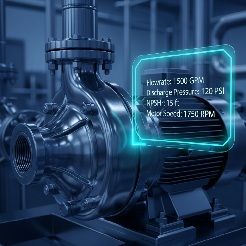
Overview of Design and Construction Specifications
| Specification | Brief Definition |
| Pressure Class Rating | A designator for a pressure-containing component, like a flange or pump casing, that defines its maximum allowable working pressure (MAWP) at a given temperature. |
| Connection Type | The method for joining the equipment’s nozzles (inlet and outlet ports) to the client’s piping system. |
| Connection Standard & Rating | A set of specifications that governs the dimensions, materials, and pressure-temperature ratings of connection components, primarily flanges, to ensure interchangeability and safety. |
| Flange Face Type | The specific design of the sealing surface of a flange where the gasket is seated. |
| Pump Nozzle Size | The nominal pipe size (NPS) in inches or nominal diameter (DN) in millimeters of the equipment’s suction and discharge connections. |
| Nozzle Configuration | The physical orientation of the suction and discharge nozzles on the equipment casing. |
| Nozzle Load Allowance | The maximum forces and moments that connected piping can exert on the equipment’s nozzles without causing casing distortion, shaft misalignment, or mechanical failure. |
| Mounting Configuration | The overall orientation of the equipment during installation. Common configurations include horizontal, vertical, and in-line. |
| Mounting Base / Feet Configuration | The method by which the equipment casing is supported and fastened to its foundation or baseplate. |
| Baseplate Design | A rigid, structural steel or cast iron frame on which both the pump and its driver are mounted. Its main function is to provide a stable foundation to maintain precise alignment. |
| Sealing Method (Primary Containment) | The system used to prevent the process fluid from leaking out of the equipment along the rotating shaft. |
| Mechanical Seal Type | A device providing a running seal between a rotating shaft and a stationary housing, consisting of two precision-lapped flat faces pressed together. |
| Mechanical Seal Arrangement | The specific configuration of two seals in a dual seal setup. |
| Seal Support System | A standardized piping arrangement, defined by API 682, that supplies fluid to the mechanical seal faces for lubrication, cooling, and to control pressure and temperature. |
| Lip Seal Type & Material | A simpler sealing device with a flexible elastomeric or plastic lip that contacts the rotating shaft to retain low-pressure lubricants and exclude contaminants. |
| Bearing Arrangement | The physical placement of the bearings relative to the impeller(s) on the shaft. |
| Bearing Type & Configuration | The type of rolling-element bearing used to support the radial and axial (thrust) loads on the shaft. |
| Bearing Lubrication Method | The method used to supply lubricant (grease or oil) to the bearings to reduce friction, dissipate heat, and prevent corrosion. |
| Heating/Cooling Jacket | An external chamber through which a thermal fluid is circulated to control the temperature of the process fluid within the equipment. |
| Insulation & Jacketing | A layer of material with low thermal conductivity to reduce heat transfer (Insulation), and a protective outer cover to shield it from damage (Jacketing). |
| Coupling Type | A mechanical component that connects the driver’s shaft to the driven equipment’s shaft to transmit torque. |
| External Paint / Coating Specification | The required standard for surface preparation and the type of coating system applied to the equipment’s exterior for corrosion protection. |
| Drains, Vents, and Flushing Connections | Small connections on the equipment casing for auxiliary functions like bleeding trapped gases (Vents), draining fluids (Drains), or flushing the system (Flushing Connections). |
| Lifting Lug Requirements | Designated, structurally sound attachment points on the equipment designed for safe lifting by cranes or hoists. |
Section 1: Core System Integration & Performance Parameters
This section covers the foundational specifications that determine the equipment’s pressure-containing capability and its physical interface with the client’s piping system. These parameters must be correctly identified at the initial stage of the sales process, as an error here can render the equipment fundamentally incompatible with the intended application.
Definition The Pressure Class Rating is a designator for a given pressure-containing component, such as a flange or pump casing, that defines its maximum allowable working pressure (MAWP) at a given temperature. It is not a direct measure of pressure but rather a reference to a standardized pressure-temperature curve for a specific material group.
Common Units
ASME/ANSI Class: A dimensionless number, often followed by symbols such as ‘#’, ‘Lb’, or ‘Lbs’ (e.g., Class 150, 150#, 150 Lb). The seven standard classes are 150, 300, 400, 600, 900, 1500, and 2500.
PN (Pression Nominale/Nominal Pressure): The European (ISO/DIN) equivalent, which indicates the approximate pressure rating in bars (e.g., PN20, PN50).
Common Unit Conversions While direct conversion is not precise due to different temperature benchmarks and material groupings, the following table provides approximate equivalents for general reference.
| ASME/ANSI Class | Approximate PN Rating (bar) |
| 150 | PN20 |
| 300 | PN50 |
| 400 | PN68 |
| 600 | PN100 / PN110 |
| 900 | PN150 |
| 1500 | PN250 / PN260 |
| 2500 | PN420 |
Examples A client requires a pump for a system with a maximum operating pressure of 40 bar at a temperature of 200°C. The material specified is carbon steel (e.g., ASTM A105). Using an ASME B16.5 pressure-temperature table, the Sales Engineer would determine the required pressure class. A Class 150 flange at this temperature may only be rated for approximately 13.8 bar, and a Class 300 flange for 43.8 bar. Therefore, a Class 300 rating would be the minimum requirement.
Advanced Knowledge The relationship between pressure, temperature, and material is fundamental to understanding pressure class ratings. For any given material and pressure class, the maximum allowable working pressure decreases as the operating temperature increases. A common and critical misunderstanding is to assume the class number represents the pressure rating in psi. For example, a Class 150 flange made from ASTM A105 carbon steel has a MAWP of 285 psig at ambient temperatures (up to 100°F or 38°C) but is rated for only 150 psig at approximately 600°F (315°C). Therefore, the class rating must be interpreted as an identifier for a specific performance curve within a standard like ASME B16.5, not as a static pressure limit. The selection process involves three steps:
Identify the client’s maximum operating pressure and temperature.
Identify the required material of construction, which corresponds to a material group in the standard.
Consult the pressure-temperature rating table for that material group to find the lowest class that meets or exceeds the required pressure at the specified temperature.
Technical Impact on Equipment The Pressure Class Rating is one of the most critical design specifications. It dictates the required wall thickness of pressure-containing components like the pump casing and nozzles, the dimensions of the flanges, and the size and number of bolts required. A higher pressure class results in a physically larger, heavier, and more costly piece of equipment. For instance, a Class 600 flange has a larger outside diameter, a larger bolt circle diameter, and requires more or larger bolts than a Class 300 flange of the same nominal pipe size, because it is constructed with more metal to withstand higher pressure. This directly impacts the equipment’s cost, weight, and installation footprint. Selecting an incorrect (too low) pressure class can lead to catastrophic failure, while over-specifying (too high) results in unnecessary cost and complexity.
1.2.1 Connection Type
Definition The method by which the equipment’s nozzles (inlet and outlet ports) are joined to the client’s piping system. The most common types are flanged, threaded, and welded connections, with flanged connections being dominant in industrial process applications.
1.2.2 Connection Standard & Rating
Definition A set of specifications that governs the dimensions, materials, and pressure-temperature ratings of connection components, primarily flanges, to ensure interchangeability and safety.
Common Units
ANSI/ASME: American National Standards Institute / American Society of Mechanical Engineers. The dominant standard in the Americas and widely used globally (e.g., ASME B16.5).
DIN: Deutsches Institut für Normung. The German standard, widely used throughout Europe.
JIS: Japanese Industrial Standards. The dominant standard in Japan and influential in other parts of Asia.
Advanced Knowledge It is critical to understand that different flange standards are not dimensionally interchangeable. For example, an ANSI Class 150 flange cannot be bolted to a DIN PN20 flange, even though their pressure ratings are similar, because their bolt circle diameters, number of bolt holes, and other dimensions are different. In the diverse Asian market, projects may be built to any of these standards. A Sales Engineer must confirm the client’s existing plant standard with absolute certainty. Specifying the wrong standard will make physical connection impossible without costly, custom-fabricated adaptors, leading to significant project delays and budget overruns.
1.2.3 Flange Face Type
Definition The specific design of the sealing surface of a flange where the gasket is seated.
Common Units
Raised Face (RF): The most common type, where the gasket surface is raised above the bolting circle face. This design concentrates bolt load on a smaller area, increasing the pressure containment capability.
Flat Face (FF): The entire face of the flange is flat. Used for mating with cast iron or other brittle material flanges to prevent cracking the mating flange.
Ring-Type Joint (RTJ): Features a groove machined into the face to accommodate a solid metal ring gasket. Used for high-pressure and high-temperature services to create a metal-to-metal seal.
Tongue and Groove (T&G) / Male and Female (M&F): Interlocking designs that provide superior gasket retention and alignment, used in specialized, high-pressure, or hazardous applications.
| Flange Face Type | Sealing Surface Description | Compatible Gasket Types | Typical Application |
| Raised Face (RF) | Gasket surface is raised above the bolting circle. | Spiral Wound, Jacketed, Flat Ring | General process, wide range of pressures/temperatures. |
| Flat Face (FF) | Gasket surface is in the same plane as the bolting circle. | Full Face (Soft Type) | Low pressure; mating with cast iron/brittle flanges. |
| Ring-Type Joint (RTJ) | A circular groove is machined into the face. | Metallic Ring Gaskets (R, RX, BX) | High-pressure (> Class 600) and high-temperature services. |
| Tongue & Groove (T&G) | One flange has a raised ring (tongue), the other a matching depression (groove). | Confined Gaskets (Spiral Wound, Flat) | High-pressure, hazardous fluids; ensures gasket containment. |
| Male & Female (M&F) | Similar to T&G but with different geometry for gasket retention. | Confined Gaskets (Spiral Wound, Flat) | High-pressure, hazardous fluids; ensures gasket containment. |
Advanced Knowledge The flange face and gasket must be treated as a system. A critical rule is that a Raised Face (RF) flange must never be bolted to a Flat Face (FF) flange. Doing so creates a point load on the FF flange, which can easily crack it, especially if it is made of a brittle material like cast iron. The proper procedure is to machine the raised face off the steel flange to create a matching flat face.
1.2.4 Pump Nozzle Size
Definition The nominal pipe size (NPS) in inches or nominal diameter (DN) in millimeters of the equipment’s suction and discharge connections.
1.2.5 Nozzle Configuration
Definition The physical orientation of the suction and discharge nozzles on the equipment casing. Common configurations for centrifugal pumps include end-suction/top-discharge, top-suction/top-discharge, and side-suction/side-discharge.
1.2.6 Nozzle Load Allowance
Definition The maximum forces and moments that the connected piping can exert on the equipment’s nozzles without causing casing distortion, shaft misalignment, or mechanical failure.
Advanced Knowledge Nozzle loads arise from factors like thermal expansion of the piping, pipe and fluid weight, and pressure effects. Excessive nozzle loads are a primary cause of equipment failure, leading to coupling and shaft misalignment, which in turn causes premature failure of bearings and mechanical seals. The American Petroleum Institute (API) Standard 610 provides tables of minimum allowable nozzle loads for centrifugal pumps used in demanding services. Equipment designed to meet or exceed these API 610 values is inherently more robust, featuring stiffer casings and more rugged support structures. For piping designers, a higher nozzle load allowance simplifies piping design, reducing the need for expensive expansion loops and supports. Therefore, a high nozzle load capability is a key indicator of the equipment’s structural integrity and directly contributes to lower total cost of ownership for the client through enhanced reliability and potentially lower installation costs.
Technical Impact on Equipment Connection specifications (type, standard, face, size, configuration) define the physical boundary between the equipment and the plant. They are non-negotiable for ensuring a leak-tight and compatible installation. Nozzle load allowance dictates the required structural strength of the pump casing, its support feet, and the baseplate. Inadequate nozzle load capacity will inevitably lead to chronic reliability issues and high maintenance costs.
Section 2: Mounting & Structural Integrity
Once the equipment’s interface with the piping system is defined, its physical support system must be specified. The mounting configuration and baseplate design are fundamental to managing operational loads, maintaining alignment between the pump and its driver, and ensuring long-term structural integrity.
Definition The overall orientation of the equipment during installation. Common configurations include horizontal (shaft parallel to the ground), vertical (shaft perpendicular to the ground), and in-line (suction and discharge nozzles are on the same axis for direct installation into a pipeline).
Definition The method by which the equipment casing is supported and fastened to its foundation or baseplate.
Common Units
Foot-Mounted: The pump casing has feet cast or fabricated at its bottom, which are bolted to the baseplate. This is common for general-purpose applications.
Centerline-Supported: The casing is supported by pedestals located on the horizontal centerline of the shaft. This design is standard for high-temperature services as specified in API 610 (OH2 type pumps).
Advanced Knowledge The choice between foot mounting and centerline support is driven by the physics of thermal expansion. In high-temperature services, the pump casing heats up and expands. In a foot-mounted design, this expansion occurs upwards from the fixed feet, causing the pump shaft’s centerline to rise relative to the motor shaft, which remains at a cooler, stable height. This vertical growth induces significant shaft misalignment. A centerline-supported design solves this problem by fixing the shaft’s centerline in space. As the casing heats up, it expands uniformly outwards and downwards from this fixed centerline, preserving the critical alignment with the motor shaft. This design feature is essential for maintaining the reliability of the coupling and bearings in any service operating at elevated temperatures.
Definition A rigid, structural steel or cast iron frame on which both the pump and its driver (e.g., electric motor) are mounted. The primary function of the baseplate is to provide a stable, flat, and coplanar foundation to maintain precise alignment between the two pieces of equipment during operation.
Advanced Knowledge Improper baseplate design and installation are a leading cause of rotating equipment failures. API 610 provides stringent requirements for baseplate design to combat these issues. Key requirements include:
Rigidity: The baseplate must be sufficiently stiff to resist deflection from nozzle loads, motor torque, and its own weight during transport and operation.
Flatness & Coplanarity: The machined mounting pads for the pump and motor must be extremely flat and coplanar. API 610 specifies that corresponding surfaces must be in the same plane within 150 µm/m (0.002 in/ft) of distance between the pads. These requirements are designed to prevent a condition known as “soft foot,” where an equipment foot does not sit flat on the baseplate. When the hold-down bolts are tightened, the equipment’s frame is distorted, which induces internal stresses and guarantees shaft misalignment, leading directly to premature bearing and seal failure. An API-compliant baseplate is an engineered system designed to prevent these common failure modes. While a less robust baseplate may have a lower initial cost, it is a false economy that will result in significantly higher maintenance costs and lower reliability for the client over the equipment’s lifecycle.
Technical Impact on Equipment The mounting configuration and baseplate design form the structural backbone of the entire equipment package. A correctly specified mounting system (e.g., centerline support for hot service) and a rigid, flat, API-compliant baseplate are fundamental prerequisites for achieving and maintaining shaft alignment. Proper alignment is the single most important factor in ensuring the long-term reliability of bearings, mechanical seals, and couplings.
Section 3: Sealing Systems & Bearing Configurations
This section examines the internal components most critical to equipment reliability: the systems that contain the process fluid (seals) and support the rotating shaft (bearings). Failures in these systems are the most frequent cause of equipment downtime and maintenance activity.
Definition The system used to prevent the process fluid from leaking out of the equipment along the rotating shaft. The two primary methods are mechanical seals and lip seals.
Definition A device that provides a running seal between a rotating shaft and a stationary housing. It consists of two precision-lapped flat faces, one rotating and one stationary, pressed together by spring force and hydraulic pressure to form a seal.
Common Units
Single Seal: One set of seal faces, suitable for non-hazardous or non-toxic fluids where minor leakage to the atmosphere is acceptable.
Dual (or Double) Seal: Two sets of seal faces (inboard and outboard) arranged in series, used for hazardous, toxic, or environmentally sensitive fluids where leakage to the atmosphere must be prevented.
Definition The specific configuration of the two seals in a dual seal setup.
Common Units
Tandem (Face-to-Back): The two seals are oriented in the same direction. The outboard seal serves as a backup or containment seal, operating at a low pressure. This arrangement is preferred for hazardous applications where secondary containment is required in case the primary seal fails.
Back-to-Back: The two seals are oriented in opposite directions, with the rotating faces on the outside. This is a common arrangement for general-purpose dual seals.
Face-to-Face: The rotating seal faces share a common stationary face. This is a compact design used when space is limited.
Definition A standardized piping arrangement, defined by API 682, that supplies a fluid to the mechanical seal faces to provide lubrication and cooling, and to control the pressure and temperature in the seal chamber.
Advanced Knowledge The selection of a seal arrangement and its support system is dictated by the properties of the process fluid and environmental regulations. For hazardous fluids where leakage is unacceptable, a dual seal is mandatory. The choice of fluid in the seal support system is critical:
Buffer Fluid (Unpressurized): Used in an API Plan 52 system. The fluid in the space between the two seals is at a pressure lower than the process pressure. If the inboard seal leaks, process fluid will leak into the buffer fluid circuit, triggering an alarm. The outboard seal contains the leakage. This is a “containment” strategy.
Barrier Fluid (Pressurized): Used in API Plan 53 (A, B, C) or Plan 54 systems. The fluid between the seals is at a pressure higher than the process pressure. This ensures that if any leakage occurs, it is the clean barrier fluid leaking into the process, and no process fluid can escape to the atmosphere. This is a “zero emission” strategy and is required for the most toxic or hazardous services. This logic forms a clear decision path: if the fluid is hazardous, a dual seal is required. If any leakage of the process fluid into a secondary loop is unacceptable for safety or environmental reasons, a pressurized barrier fluid system must be specified.
Definition A simpler sealing device consisting of a flexible elastomeric or plastic lip that contacts the rotating shaft to retain low-pressure lubricants and exclude contaminants. They are often used as bearing isolators rather than for primary process containment.
Common Units
Types: Single Lip (retains lubricant), Double Lip (retains lubricant and excludes contaminants).
Materials:
Nitrile (NBR): Good resistance to petroleum oils and fuels; cost-effective.
Fluoroelastomer (FKM, Viton®): Excellent resistance to high temperatures, chemicals, and oils.
PTFE: Extremely wide temperature range and superior chemical resistance; low friction.
Definition The physical placement of the bearings relative to the impeller(s) on the shaft.
Common Units
Overhung (OH): The impeller is mounted on the end of the shaft, cantilevered beyond the bearings (e.g., API 610 types OH1, OH2).
Between-Bearing (BB): The impeller(s) are mounted on the shaft between two bearing housings (e.g., API 610 types BB1 through BB5).
Definition The type of rolling-element bearing used to support the radial and axial (thrust) loads on the shaft.
Common Units
Deep Groove Ball Bearings: Versatile and common; handle both radial and moderate axial loads.
Angular Contact Ball Bearings: Designed to handle combined radial and high axial loads. Often used in pairs to handle thrust in both directions.
Cylindrical Roller Bearings: Have a high radial load capacity but little to no axial load capacity.
Definition The method used to supply lubricant (grease or oil) to the bearings to reduce friction, dissipate heat, and prevent corrosion.
Common Units
Grease: A semi-solid lubricant. Simple, low-cost, and good for lower speeds and loads. Resists leakage and contamination.
Oil Bath / Splash: The bearing housing contains a sump of oil. Lubrication is achieved either by the bearings dipping into the oil (bath) or by a slinger ring that splashes oil onto the bearings.
Oil Mist: A centralized system atomizes oil into fine particles (1-3 microns) which are conveyed by low-pressure air to the bearing housing. This provides a continuous supply of fresh, clean oil.
Pure Mist: The oil mist is the sole source of lubrication.
Purge Mist: The oil mist is used to purge the bearing housing headspace above a conventional oil sump, preventing contamination and providing some supplemental lubrication.
Advanced Knowledge The choice of lubrication method has a profound impact on bearing life and overall equipment reliability. While oil bath is common, it is susceptible to contamination as wear particles remain suspended in the sump. Oil mist lubrication is a technically superior method that addresses these shortcomings. It delivers a continuous, metered supply of clean lubricant, which significantly reduces friction and lowers bearing operating temperatures by 10-15°C. Furthermore, the positive pressure inside the bearing housing prevents the ingress of atmospheric contaminants like dust and moisture. This combination of superior lubrication and cleanliness can reduce lubrication-related bearing failures by up to 90%. Although an oil mist system has a higher initial capital cost, it provides a strong Total Cost of Ownership (TCO) advantage through dramatically reduced maintenance, lower oil consumption, and increased equipment uptime.
Technical Impact on Equipment The seal and bearing systems are the heart of rotating equipment reliability. The sealing system specification is driven by process fluid characteristics and safety/environmental regulations. The bearing and lubrication system specification is driven by the loads (radial and axial) and speed of the application. A failure in either system will result in immediate equipment shutdown.
Section 4: Operational Features & Accessories
This section details ancillary systems and components that are specified based on the properties of the process fluid, the operating environment, or the requirements of the drive system. These features are often optional but can be critical for ensuring safe and efficient operation in specific applications.
Definition An external chamber, either integral to or bolted onto the equipment casing, through which a thermal fluid is circulated to control the temperature of the process fluid within the equipment.
Common Units
Heating Media: Steam, hot oil, or specialized heat transfer fluids are used to heat the process fluid.
Cooling Media: Water, glycol solutions, or refrigerants are used to cool the process fluid.
Examples Heating jackets are essential for applications involving fluids that are solid or highly viscous at ambient temperatures, such as bitumen, heavy fuel oil, molten sulfur, or chocolate. The jacket maintains the fluid in a liquid state, allowing it to be pumped effectively and preventing solidification within the casing, which could damage the equipment. Cooling jackets may be used to remove excess heat from exothermic reactions or to cool mechanical seals.
Definition
Insulation: A layer of material with low thermal conductivity (e.g., fiberglass, mineral wool, calcium silicate, aerogel) applied to the exterior of equipment to reduce heat transfer.
Jacketing (or Cladding): A protective outer cover, typically made of aluminum or stainless steel, installed over the insulation to shield it from weather, moisture, and mechanical damage.
Advanced Knowledge Heating jackets and insulation are complementary systems for thermal management. A heating jacket is an active system that adds or removes heat, while insulation is a passive system that prevents heat loss or gain to the environment. When a heating jacket is specified, insulation is almost always required. Operating a heated pump without insulation results in significant energy waste and creates a severe burn hazard for personnel due to high external surface temperatures. Therefore, when a client specifies a heating jacket, the Sales Engineer must immediately inquire about the insulation and jacketing requirements to ensure a safe and energy-efficient system.
Definition A mechanical component that connects the shaft of the driver (e.g., motor) to the shaft of the driven equipment (e.g., pump) to transmit torque. Flexible couplings also serve the critical function of accommodating small amounts of shaft misalignment (parallel, angular, and axial).
Common Units
Rigid Couplings: Offer a solid connection with no flexibility. They are used only when shafts can be perfectly aligned.
Flexible Couplings (Metallic): Use metallic elements to transmit torque and accommodate misalignment.
Gear Coupling: Transmits high torque via meshing gear teeth. Requires lubrication.
Grid Coupling: Uses a serpentine steel grid in slotted hubs. Torsionally flexible and absorbs shock. Requires lubrication.
Disc/Diaphragm Coupling: Uses thin metal discs or diaphragms to transmit torque. Torsionally rigid and maintenance-free.
Flexible Couplings (Elastomeric): Use a flexible polymer element (e.g., rubber, polyurethane) to transmit torque.
Jaw Coupling: Two hubs with interlocking jaws are separated by an elastomeric “spider.” Simple, low-cost, and maintenance-free.
Tyre Coupling: A flexible rubber or polyurethane “tyre” is bolted between two hubs. Excellent for absorbing shock and vibration and accommodates significant misalignment.
| Coupling Category | Common Types | Misalignment Tolerance | Vibration Damping | Maintenance |
| Rigid | Flange, Sleeve | None | Poor | Low |
| Metallic Flexible | Gear, Grid, Disc | Moderate | Low | Lubrication Required (Gear/Grid) |
| Elastomeric Flexible | Jaw, Tyre, Pin & Bush | High | Excellent | None |
Advanced Knowledge The selection of a shaft coupling involves a trade-off between torsional stiffness, misalignment tolerance, vibration damping, and maintenance requirements. Rigid couplings provide the highest torsional stiffness but are intolerant of any misalignment. Metallic flexible couplings like gear and grid types can transmit very high torque but offer limited vibration damping and require periodic lubrication. Elastomeric couplings are excellent at absorbing shock and vibration, require no maintenance, and can accommodate more misalignment, but they typically have lower torque capacity and are limited by the temperature tolerance of the polymer element. The correct choice depends on a careful evaluation of the application’s specific needs for precision, robustness, and maintenance.
Technical Impact on Equipment These features adapt the standard equipment for specific process requirements. A heating jacket is essential for high-viscosity fluids. Insulation is critical for energy efficiency and safety. The coupling choice directly impacts the system’s tolerance for misalignment and its dynamic behavior (vibration), affecting the reliability of the entire drive train.
Section 5: Finalization, Safety & Maintenance Provisions
This final section covers specifications related to the equipment’s external protection, provisions for safe maintenance, and features that facilitate handling.
Definition The required standard for surface preparation and the type of coating system to be applied to the equipment’s exterior surfaces for corrosion protection and appearance.
Common Units Surface preparation standards are defined jointly by SSPC (The Society for Protective Coatings) and NACE International. The standard specifies the degree of cleanliness required before painting.
SSPC-SP 6 / NACE No. 3, Commercial Blast Cleaning: All visible oil, grease, dust, and dirt are removed. Tightly adhering mill scale, rust, and old coatings may remain on up to 33% of each unit area of the surface.
SSPC-SP 10 / NACE No. 2, Near-White Blast Cleaning: Same as above, but staining and tightly adhered matter are limited to no more than 5% of each unit area.
SSPC-SP 5 / NACE No. 1, White Metal Blast Cleaning: Complete removal of all visible rust, mill scale, paint, and foreign matter. The surface will have a uniform, gray-white metallic appearance.
| SSPC/NACE Standard | Name | Description of Cleanliness |
| SP 6 / NACE 3 | Commercial Blast | Tightly adhered matter may remain on up to 33% of the surface. |
| SP 10 / NACE 2 | Near-White Blast | Tightly adhered matter is limited to 5% of the surface. |
| SP 5 / NACE 1 | White Metal Blast | 100% free of all visible matter; uniform metallic appearance. |
Advanced Knowledge The longevity and performance of any protective coating system are determined more by the quality of the surface preparation than by the quality of the paint itself. A high-performance coating applied to a poorly prepared surface will fail prematurely due to a lack of adhesion. The difference between a Commercial Blast (SP 6) and a Near-White Blast (SP 10) is the allowable percentage of remaining surface contaminants. While this may seem minor, for equipment in highly corrosive environments (e.g., coastal or offshore facilities), specifying the higher standard (SP 10 or SP 5) is critical for ensuring the coating system achieves its designed service life. Educating the client that reducing costs on surface preparation will compromise their investment in the coating system is essential.
Definition Small, typically threaded or flanged connections on the equipment casing that serve auxiliary functions.
Vents: Located at the highest point of a casing or seal chamber to allow trapped gases or vapors to be bled off. This is critical for ensuring the pump is fully primed with liquid before startup.
Drains: Located at the lowest point of a casing or bearing housing to allow the complete drainage of process fluid or lubricating oil for maintenance.
Flushing Connections: Ports that allow for the introduction of an external fluid to flush the casing or seal chamber for cleaning or to provide a clean fluid to the seals (as in API Plan 32).
Definition Designated, structurally sound attachment points on the equipment or its components, designed for safe lifting by cranes or hoists.
Advanced Knowledge A critical safety distinction must be made regarding lifting lugs. Lugs integrally cast or welded onto major individual components, such as the motor or the pump bearing housing, are designed only to lift the weight of that individual component. They are not rated to lift the entire pump-motor-baseplate assembly. The complete assembly must be lifted using designated lifting points on the baseplate itself. Attempting to lift the entire unit by the motor or pump lifting lugs can lead to catastrophic failure of the lug, dropping the load and creating an extremely dangerous situation. All lifting operations must comply with local safety regulations and be performed by trained personnel using properly rated rigging equipment.
Technical Impact on Equipment These specifications ensure the equipment is protected from environmental corrosion, can be safely operated and maintained, and can be handled correctly during installation and removal. While they may seem like minor details, they are essential for the overall safety, serviceability, and longevity of the equipment.