
Fluid & Material Properties
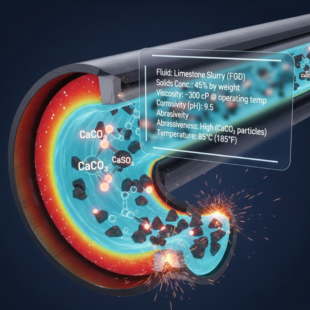
Overview of Fluid Properties for Equipment Specification
| Specification | Brief Definition |
| Fluid Name, Chemical Composition & Concentration | The complete and unambiguous identification of the process fluid, including its primary chemical constituents and the concentration of each component. |
| Fluid Flammability & Explosiveness | Describes the ability of a fluid’s vapors to ignite in the presence of an ignition source and sustain combustion. |
| Fluid Toxicity | The degree to which a fluid can cause injury or illness to biological organisms, particularly humans, upon exposure. |
| Chemical Reactivity | The tendency of a fluid to undergo a vigorous chemical reaction, such as polymerization or decomposition, which can release large amounts of energy. |
| Fluid Operating Temperature Range | The full spectrum of temperatures the fluid will experience throughout all operational phases, including minimum, normal, and maximum. |
| Fluid State | The physical form of the process medium (e.g., liquid, gas, slurry) under the specified operating conditions of temperature and pressure. |
| Vapor Pressure at Operating Temperature | The absolute pressure at which a liquid will begin to boil and turn into a vapor at a specific temperature. |
| Specific Gravity (SG) & Density | Density (ρ) is a substance’s mass per unit volume; Specific Gravity (SG) is the dimensionless ratio of the fluid’s density to that of water. |
| Viscosity | A measure of a fluid’s internal resistance to flow and shear, often described as its “thickness”. |
| Presence of Entrained or Dissolved Gases | Quantifies the amount of gas present within a liquid, either as undissolved bubbles (entrained) or molecularly dispersed in the solution (dissolved). |
| pH Level | A quantitative measure of the acidity or alkalinity of an aqueous solution on a logarithmic scale. |
| Presence of Chlorides, Sulfides, or Halogens | Refers to the concentration of specific, highly aggressive ions or compounds within the fluid, such as chloride ions (Cl⁻) or hydrogen sulfide (H₂S). |
| Tendency to Scale, Precipitate, or Polymerize | The propensity of a fluid to form solid deposits (fouling) on the internal surfaces of equipment. |
| Oxygen Compatibility | A measure of the suitability of a fluid or material for use in environments with high concentrations of oxygen, focusing on ignition and combustion resistance. |
| Solids Content (% by weight/volume) | Quantifies the amount of solid material present in a slurry, expressed either as a percentage of total mass or total volume. |
| Particle Size, Distribution, & Shape | Describes the physical characteristics of the solid particles, including the largest dimension, the statistical range of sizes, and their geometry. |
| Particle Hardness & Abrasiveness | Hardness is a solid’s resistance to scratching or indentation; abrasiveness is the capacity of these particles to wear away equipment surfaces. |
| Boiling Point at Atmospheric Pressure | The temperature at which a liquid’s vapor pressure equals the surrounding atmospheric pressure, causing it to change into a vapor. |
| Freezing / Pour Point | The temperature at which a liquid turns into a solid (Freezing Point) or, for complex mixtures like oils, the lowest temperature at which it will still flow (Pour Point). |
| Specific Heat Capacity | The amount of heat energy required to raise the temperature of a unit mass of a substance by one degree without a change in phase. |
| Thermal Conductivity | A measure of a material’s ability to conduct heat, quantifying the rate at which heat is transferred through it. |
| Latent Heat of Vaporization | The amount of heat energy that must be added to a unit mass of a liquid at its boiling point to convert it entirely into a gas at the same temperature. |
| Surface Tension | A property of a liquid’s surface that allows it to resist an external force, caused by the cohesive forces between the liquid’s molecules. |
| Shear Sensitivity | Describes how a fluid’s viscosity changes when it is subjected to mechanical stress or “shear.” |
| Compressibility | A measure of the relative volume change of a fluid in response to a change in pressure. |
The reliability, efficiency, and safety of industrial fluid handling systems—including pumps, valves, and piping—hinge on precise equipment selection. The single most critical step in this process is the rigorous, front-end characterization of the process medium. Misunderstanding the fluid is the primary cause of premature equipment failure, costly downtime, and safety incidents.
This guide provides a comprehensive framework for understanding the most critical fluid and material specifications. It is essential to distinguish between intrinsic properties (the fluid’s inherent characteristics, like viscosity and corrosivity) and extrinsic parameters (system demands, like flow rate). The fluid’s properties are the cause, and the system’s performance is the effect; therefore, a deep understanding of the fluid must precede any equipment selection.
This guide is structured to mirror the practical workflow of a sales engineer confronting a new application. It deliberately departs from a simple alphabetical or categorical list of properties. Instead, it prioritizes information in a logical sequence, beginning with the non-negotiable aspects of fluid identification and safety. This foundational assessment serves as the “Go/No-Go” gate; only after a fluid is precisely identified and its inherent hazards are understood can one proceed to sizing and performance calculations.
Section 1: Foundational Fluid Identification & Safety Assessment
The initial phase of any equipment specification process must be a rigorous identification and safety assessment of the process fluid. Before any performance characteristics are considered, the fundamental nature of the fluid—its chemical identity and inherent hazards—must be established without ambiguity. This section addresses the properties that are paramount for ensuring personnel safety, environmental protection, and basic material compatibility. An oversight at this stage can render all subsequent engineering calculations irrelevant and introduce unacceptable risks.
Definition This is the complete and unambiguous identification of the process fluid. It encompasses not only the common or trade name but also a detailed breakdown of its primary chemical constituents and the concentration of each component. For simple fluids, this may be a single chemical and its purity. For complex mixtures, such as hydraulic oils, metalworking fluids, or industrial chemicals, this includes the base fluid type (e.g., mineral oil, water, synthetic ester) and a comprehensive list of all functional additives (e.g., corrosion inhibitors, anti-wear agents, emulsifiers, biocides). Concentration is typically expressed as a percentage by weight (% wt) or percentage by volume (% vol). This parameter is the definitive starting point for all subsequent analysis, as every other fluid property is a function of its chemical makeup.
Common Descriptors Fluid composition is communicated in several standard formats. The most reliable and comprehensive source is the Safety Data Sheet (SDS), which is a regulatory requirement for hazardous chemicals. Information may also be presented as:
Chemical Formula: An unambiguous representation (e.g., H2SO4 for sulfuric acid, NaOH for sodium hydroxide).
CAS Number: A unique numerical identifier assigned by the Chemical Abstracts Service (e.g., 7664-93-9 for sulfuric acid).
Common or Industrial Name: Widely used but potentially ambiguous names (e.g., Caustic Soda for sodium hydroxide, Muriatic Acid for hydrochloric acid).
Trade Name: A brand name (e.g., Dowtherm™ A, Krytox™) which often refers to a family of products with different properties.
Classification: For lubricants or hydraulic fluids, this includes the base oil type and an industry classification (e.g., Mineral Oil, ISO VG 46).
Examples
Simple Chemical: “Sulfuric Acid, 98% concentration by weight”.
Aqueous Solution: “Sodium Hydroxide, 50% solution in water”.
Hydraulic Fluid: “Petroleum-based hydraulic fluid, ISO Viscosity Grade 46, with anti-wear (AW) and rust & oxidation (R&O) inhibitor additives”.
Metalworking Fluid: “Soluble oil concentrate, containing 60% severely refined mineral oil, emulsifiers, and biocides, for dilution to 5% in water”.
Advanced Knowledge A critical procedural discipline for a sales engineer is to never rely solely on a common or trade name provided by a customer. These names can be dangerously misleading and often obscure the true chemical nature of the fluid. A product generically called an “industrial cleaner” could be a benign, neutral pH detergent or a highly corrosive acid. Similarly, a trade name like “Therminol®” refers to an entire family of heat transfer fluids, each with vastly different chemical compositions, operating temperature ranges, and material compatibility requirements. The only way to ensure an accurate specification is to obtain the fluid’s Safety Data Sheet (SDS). The fundamental skill for a sales engineer is not just asking, “What is the fluid?” but rather, “May I have the SDS for the fluid?” This shifts the conversation from informal identification to rigorous verification, which is the cornerstone of professional risk management and accurate engineering.
Technical Impact on Equipment The chemical composition is the single most important factor governing the selection of equipment materials. Every component that comes into contact with the fluid—the pump casing, impeller, piping, valves, gaskets, and mechanical seal faces—must be chemically compatible. Incompatibility leads to rapid degradation and failure. For example, certain chemicals can cause elastomers in seals and gaskets to swell, crack, or dissolve, resulting in leaks. Aggressive fluids can corrode metallic components, leading to loss of structural integrity and eventual catastrophic failure.
Furthermore, the presence of seemingly minor components or impurities can have an outsized impact on equipment longevity, often proving more critical than the primary fluid. For instance, a process fluid that is 99.5% water may appear benign. However, if the remaining 0.5% contains a high concentration of chloride ions (e.g., from dissolved salts), it can initiate severe localized corrosion, such as pitting or crevice corrosion, on standard stainless steel grades like 316. These forms of attack can perforate the material and cause failure much faster than general corrosion. Similarly, in a lubricating oil, it is the small percentage of anti-wear and extreme-pressure additives that determines the fluid’s ability to protect bearings and gears, not the base oil itself. Therefore, a sales engineer must scrutinize the entire chemical composition, as the most aggressive and rapid failure modes are frequently triggered by these trace components.
Definition This property describes the ability of a fluid’s vapors to ignite in the presence of an ignition source and sustain combustion. It is defined by several key parameters:
Flash Point: The lowest temperature at which a liquid gives off enough vapor to form an ignitable mixture with air near its surface.
Fire Point: The temperature at which the vapor will continue to burn for at least 5 seconds after ignition. It is typically slightly higher than the flash point.
Autoignition Temperature: The lowest temperature at which a substance will spontaneously ignite in a normal atmosphere without an external ignition source.
Flammable/Explosive Limits: The concentration range of a gas or vapor in air (usually expressed as a volume percentage) that will support combustion. The range is bounded by the Lower Explosive Limit (LEL) and the Upper Explosive Limit (UEL). A mixture below the LEL is “too lean” to burn, while a mixture above the UEL is “too rich”.
Common Descriptors Flammability is most often communicated through standardized classification systems. The U.S. Occupational Safety and Health Administration (OSHA) categorizes flammable and combustible liquids into classes (e.g., Class IA, IB, IC for flammables; Class II, IIIA, IIIB for combustibles) based on their flash points and boiling points. A globally recognized and easily interpreted system is the National Fire Protection Association (NFPA) 704 standard, which uses a diamond-shaped placard. The red quadrant of the diamond indicates the flammability hazard on a scale of 0 (will not burn) to 4 (extremely flammable).
Examples
Gasoline: Flash Point -43°C; NFPA Flammability Rating 3.
Acetone: Flash Point -20°C; NFPA Flammability Rating 3.
Diesel Fuel: Flash Point >52°C; NFPA Flammability Rating 2.
Mineral Oil: Flash Point >93.3°C; NFPA Flammability Rating 1.
Advanced Knowledge The distinction between a “flammable” liquid (flash point < 37.8°C / 100°F) and a “combustible” liquid (flash point > 37.8°C / 100°F) has critical implications related to the fluid’s operating temperature. A fluid that is classified as combustible and considered relatively safe at ambient temperature can become a significant fire hazard if it is heated. According to OSHA regulations, when a combustible liquid is heated for use to within 16.7°C (30°F) of its flash point, it must be handled with the same safety precautions as a more volatile flammable liquid. For example, a heat transfer oil with a flash point of 160°C is a combustible liquid. If its normal operating temperature is 150°C, it is within the hazardous proximity to its flash point. In this scenario, specifying standard, non-rated electrical equipment would be a dangerous error. The system would require equipment rated for hazardous locations (e.g., explosion-proof motors) to prevent ignition of vapors. A sales engineer must therefore compare the fluid’s flash point against its maximum operating temperature, not just its ambient state.
Technical Impact on Equipment Fluid flammability is a primary driver of equipment selection for safety. For applications involving flammable fluids, especially where vapors can accumulate, equipment must be designed to eliminate potential ignition sources. This includes:
Explosion-Proof Motors and Controls: Electrical equipment must be specified with appropriate hazardous location ratings (e.g., ATEX in Europe, Class/Division in North America) to ensure that any internal sparks are contained and cannot ignite external vapors.
Grounding and Bonding: The system must be properly grounded and all components bonded together to prevent the buildup and discharge of static electricity, which can be a potent ignition source during fluid transfer.
Sealing Systems: High-integrity sealing is required to prevent the escape of flammable vapors. This may involve using dual mechanical seals with a non-flammable barrier fluid, or sealless pump designs like magnetic drive pumps.
Material Selection: Materials that could generate sparks upon impact (e.g., certain combinations of metals) may be prohibited.
Ventilation and Storage: The design of the surrounding area, including ventilation and the use of approved safety cabinets for storage, is also governed by the fluid’s flammability.
Definition Toxicity refers to the degree to which a fluid can cause injury or illness to biological organisms, particularly humans, upon exposure. Exposure can occur through three primary routes: inhalation of vapors, direct skin or eye contact, and ingestion. The severity of the health effect depends on the chemical’s intrinsic hazardous properties, the concentration, and the duration of exposure.
Common Descriptors The toxicity of a fluid is detailed in Section 2 (Hazards Identification) and Section 11 (Toxicological Information) of its SDS. It is communicated through:
GHS Pictograms: Standardized symbols such as the skull and crossbones for acute toxicity or the health hazard symbol for carcinogenicity.
Hazard Statements: Phrases that describe the nature of the hazard (e.g., “Fatal if swallowed,” “Causes severe skin burns and eye damage”).
Occupational Exposure Limits (OELs): Legally mandated or recommended airborne concentration limits to which workers can be exposed, such as the Permissible Exposure Limit (PEL) from OSHA or the Threshold Limit Value (TLV) from ACGIH.
NFPA 704 Diamond: The blue (health) quadrant provides a rating from 0 (no hazard) to 4 (can be lethal).
Examples
Ammonia (NH3): Acutely toxic by inhalation, corrosive to skin and eyes. NFPA Health Rating: 3.
Benzene (C6H6): A known human carcinogen with long-term exposure risks. NFPA Health Rating: 2.
Polychlorinated Biphenyls (PCBs): Historically used in some hydraulic and transformer fluids, now heavily regulated due to their persistence and ability to cause skin irritation and liver damage.
Strong Acids (e.g., Hydrofluoric Acid): Extremely corrosive and can cause severe, deep-tissue burns upon contact. NFPA Health Rating: 4.
Advanced Knowledge When specifying equipment for toxic fluids, the focus must extend beyond preventing leaks during normal operation to ensuring safety during routine maintenance and potential upset conditions. A pump with a standard single mechanical seal might offer adequate containment while running. However, the procedure for replacing that seal inevitably exposes maintenance personnel to the hazardous fluid. A more comprehensive and responsible engineering specification considers this entire lifecycle. This involves recommending not just the core equipment but an entire system architecture designed for safe handling. Such a system would include isolation valves on both the suction and discharge lines, along with dedicated drain and vent connections. This configuration allows the pump to be safely isolated from the process, drained of the toxic fluid, and flushed with a benign cleaning agent before any maintenance work begins. This approach minimizes personnel exposure and demonstrates a superior level of safety consciousness and customer care, elevating the sales engineer from a component supplier to a trusted safety advisor.
Technical Impact on Equipment The toxicity of a fluid dictates the required level of containment integrity for the equipment. For moderately toxic fluids, high-quality single mechanical seals may be sufficient. However, for highly toxic, carcinogenic, or lethal substances, the goal is zero fugitive emissions. This mandates the selection of advanced sealing technologies:
Sealless Pumps: Magnetic drive or canned motor pumps provide primary containment with no dynamic seals to the atmosphere, offering the highest level of fluid containment.
Dual Mechanical Seals: These arrangements use two sets of seals with a barrier fluid in between. Pressurized barrier systems (e.g., API Plan 53A/B/C or 54) ensure that if a leak occurs, the clean barrier fluid leaks into the process or to the atmosphere, rather than the toxic process fluid leaking out.
Personal Protective Equipment (PPE): The fluid’s toxicity directly informs the required PPE for anyone operating or maintaining the equipment, including specific types of gloves, respiratory protection, and chemical-resistant clothing.
Definition Chemical reactivity describes the tendency of a fluid to undergo a vigorous chemical reaction, such as polymerization, decomposition, or condensation, which can release large amounts of energy. This is distinct from corrosion, which is a slow degradation of material. Reactive chemicals are often termed “unstable” and can be sensitive to triggers like heat, pressure, shock, or contact with a catalyst.
Common Descriptors A fluid’s reactivity is highlighted in its SDS, often in sections detailing stability and reactivity. The most prominent and immediate indicator is the NFPA 704 diamond’s yellow (instability) quadrant, which rates the hazard from 0 (stable) to 4 (may detonate). Terms like “unstable liquid” or “self-reactive” are also used.
Examples
Ethylene Oxide: Can undergo hazardous polymerization that can be explosive if not inhibited.
Acetylene: Can decompose explosively under certain pressure conditions.
Nitroglycerin: Highly sensitive to shock and can detonate readily. NFPA Instability Rating: 4.
Ammonium Nitrate: Can detonate if subjected to a strong initiating source or heated under confinement. NFPA Instability Rating: 3.
Advanced Knowledge For highly reactive fluids, the design of the entire fluid circuit is as critical as the selection of the primary equipment itself. Seemingly minor design flaws in the piping system can create localized conditions that initiate a runaway reaction. For example, consider a system pumping a monomer that is prone to polymerization when heated. A common method for controlling flow in a centrifugal pump system is to use a bypass line with a throttling valve (e.g., a globe valve). The intense fluid shear and energy dissipation that occurs as the fluid passes through the partially closed valve generates significant localized heat. Even if the bulk temperature of the fluid remains within safe limits, this “hot spot” at the valve could be sufficient to initiate polymerization. The polymer could then build up, cause a blockage, and potentially lead to a dangerous pressure increase or a runaway reaction. A superior system design would avoid this risk by controlling the pump’s flow rate with a variable speed drive (VSD), which eliminates the need for a high-shear throttling valve. A sales engineer who understands these system-level interactions can propose a solution that is not only safer and more reliable but often more energy-efficient, showcasing a higher level of application expertise.
Technical Impact on Equipment Handling chemically reactive fluids imposes severe constraints on equipment design and selection to ensure safety:
Material Selection: Materials of construction must be chosen to be non-catalytic to the specific reaction. Trace elements in certain alloys could inadvertently act as a catalyst.
Temperature and Pressure Control: The system must have precise and reliable controls to keep the fluid well within its stable temperature and pressure range. This may require cooling jackets on pumps and vessels, as well as pressure relief systems.
Avoidance of Ignition/Initiation Sources: Equipment must be designed to minimize heat generation from friction, avoid high shear rates, and be protected from mechanical shock or impact.
System Geometry: The design of the fluid path is critical. Dead legs, crevices, or areas of low flow where the fluid can stagnate and begin to react must be eliminated. The system must be designed to be fully drainable.
Section 2: Primary Operating Conditions & Physical State
After establishing the fluid’s identity and inherent hazards, the next logical step is to define the physical conditions under which the equipment must perform. Temperature, physical state, and vapor pressure are fundamental parameters that form the basis for all subsequent hydraulic calculations, material selections, and performance predictions. These properties describe the “environment” the equipment will experience.
Definition The fluid operating temperature range specifies the full spectrum of temperatures the fluid will experience throughout all operational phases. This includes the minimum temperature (e.g., during a cold startup in an unheated facility), the normal operating temperature, and the maximum temperature (e.g., during peak load or process upset conditions).
Common Units Degrees Celsius (°C), Degrees Fahrenheit (°F), Kelvin (K).
Examples
Chilled Water System: Min: 2°C, Normal: 7°C, Max: 15°C.
Hot Oil Heat Transfer System: Min: 15°C (ambient startup), Normal: 250°C, Max: 280°C.
Hydraulic System (Outdoor): Min: -20°C, Normal: 60°C, Max: 95°C.
Advanced Knowledge While the maximum operating temperature is often the primary focus due to concerns about material strength and fluid degradation, the minimum temperature is equally critical and frequently overlooked. Ignoring the cold-start condition can lead to significant operational problems or outright equipment failure. For example, a pump may be specified for a viscous fluid based on its viscosity at a normal operating temperature of 90°C. At this temperature, the fluid may be easily handled by a standard centrifugal pump. However, if the system is started from a cold, ambient temperature of 5°C, the fluid’s viscosity could increase by several orders of magnitude. This dramatic increase in viscosity can lead to several failure modes: the pump motor may not have enough torque to start, resulting in an overload trip or stall; the suction line friction losses could become so high that the pump cavitates severely upon startup; or standard elastomer seals could become brittle at low temperatures and fracture. A thorough sales engineer always inquires about the entire operational cycle, including startup and shutdown conditions, to specify a robust solution. This might involve recommending a steam or electric heating jacket for the pump, a larger motor to handle the cold-start torque, or selecting a positive displacement pump, which is inherently better suited for high-viscosity applications.
Technical Impact on Equipment Temperature is a master variable that influences nearly every other fluid property and equipment design choice:
Fluid Properties: Temperature has a profound effect on viscosity (viscosity of liquids decreases with increasing temperature), density (density generally decreases with increasing temperature), and vapor pressure (vapor pressure increases exponentially with temperature). These changes directly impact pump performance and the risk of cavitation.
Material Selection:
Metals: The mechanical strength (tensile and yield strength) of metals decreases at elevated temperatures. Materials must be selected to retain sufficient strength at the maximum operating temperature.
Elastomers and Plastics: Non-metallic components like seals, gaskets, and linings have strict temperature limits. High temperatures can cause them to soften, degrade, or extrude, while low temperatures can cause them to become brittle and crack. For example, certain grades of Viton are incompatible with some corrosion inhibitors at temperatures above 60°C (140°F).
Thermal Expansion: Both the fluid and the equipment components will expand when heated. This must be accounted for in the design of piping (e.g., with expansion loops) and in the internal clearances of rotating equipment to prevent seizure.
Auxiliary Systems: Extreme temperatures necessitate auxiliary systems. High temperatures may require cooling jackets on pump bearing frames or seal chambers, or external heat exchangers to cool the process fluid. Low temperatures may require heating jackets or heat tracing on pumps and piping to maintain fluidity.
Definition The fluid state describes the physical form of the process medium under the specified operating conditions of temperature and pressure. The primary states relevant to industrial equipment are:
Liquid: A substance that is largely incompressible and takes the shape of its container.
Gas: A substance that is compressible and expands to fill its container.
Slurry: A two-phase mixture consisting of solid particles suspended in a liquid.
Multi-phase: A complex mixture of two or more distinct phases that are not chemically combined, such as immiscible liquids (e.g., oil and water), or a combination of liquid(s) and gas (e.g., unprocessed wellhead fluid).
Common Descriptors The state is typically described by name (Liquid, Gas). For slurries, the solids concentration is also required (e.g., % solids by weight). For multi-phase flows, the Gas Volume Fraction (GVF), which is the ratio of the volume of gas to the total volume of the mixture, is a key parameter.
Examples
Liquid: Water, diesel fuel, hydraulic oil.
Gas: Natural gas, nitrogen, compressed air.
Slurry: Mining tailings, paper pulp, wastewater sludge.
Multi-phase: Unprocessed crude oil from a wellhead (a mixture of oil, water, natural gas, and sand).
Advanced Knowledge A critical consideration is that the fluid state may not be constant throughout a given process. A fluid can undergo a phase change as it moves through a system due to variations in pressure and temperature. For example, a high-pressure liquid passing through a control valve or orifice will experience a significant pressure drop. If the downstream pressure falls below the fluid’s vapor pressure at that temperature, the liquid will partially vaporize, or “flash,” creating a two-phase (liquid-gas) flow. This flashing phenomenon can be extremely destructive, causing severe erosion damage to valve internals and downstream piping that is mechanistically similar to cavitation. It also introduces instability into the process. A sales engineer must therefore analyze the entire process schematic, not just the conditions at the equipment inlet, to anticipate potential phase changes. This allows for the correct specification of equipment designed to handle such transitions, such as valves with anti-cavitation or anti-flashing trim, or properly sized orifices to control the pressure drop.
Technical Impact on Equipment The fluid state is the most fundamental factor in determining the type of equipment to be used. Each class of machinery is specifically designed for a particular phase:
Liquids: Handled by pumps (e.g., centrifugal, positive displacement). Running a standard liquid pump with a significant amount of gas can lead to overheating, seal failure, and loss of performance (gas binding).
Gases: Handled by compressors, fans, or blowers. Introducing liquid into a gas compressor can cause severe mechanical damage (a condition known as “slugging”).
Slurries: Require specialized slurry pumps, which are built with robust materials to resist abrasion and have larger internal clearances to prevent clogging.
Multi-phase: Require highly specialized multi-phase pumps (e.g., helico-axial pumps) designed to handle varying gas volume fractions without the need for upstream separation of the phases. Using a standard centrifugal pump in multi-phase service would lead to rapid performance degradation and failure.
Definition Vapor pressure is the pressure exerted by the vapor of a substance in thermodynamic equilibrium with its condensed phases (solid or liquid) at a given temperature in a closed system. In simpler terms for fluid handling, it is the absolute pressure at which a liquid will begin to boil and turn into a vapor at a specific temperature. It is a direct measure of a liquid’s volatility; liquids with high vapor pressures (e.g., gasoline) evaporate easily, while those with low vapor pressures (e.g., mercury) do not.
Common Units Absolute pressure units are required. Common units include pounds per square inch absolute (psia), bar absolute (bara), and kilopascals absolute (kPa abs).
Examples
Water: At 20°C (68°F), vapor pressure is 0.023 bara (0.34 psia). At 100°C (212°F), it is 1.013 bara (14.7 psia), equal to standard atmospheric pressure.
Propane: At 20°C (68°F), vapor pressure is approximately 8.5 bara (124 psia).
Ammonia: At 20°C (68°F), vapor pressure is approximately 8.6 bara (125 psia).
Advanced Knowledge Vapor pressure is not a static property; it is highly dependent on temperature. This relationship is non-linear and typically exponential. A small increase in fluid temperature can cause a large increase in its vapor pressure. This is a critical consideration often overlooked in system design, which can lead to unexpected cavitation problems. For example, a pumping system may be designed to handle water at 70°C, where its vapor pressure is about 0.31 bara. The system’s available suction pressure may provide a healthy safety margin against this value. However, if a process upset or a change in operating conditions causes the water temperature to rise to 90°C, the vapor pressure increases significantly to about 0.70 bara. This sharp increase in vapor pressure directly reduces the available margin against boiling (as defined in the Net Positive Suction Head calculation). This reduction could easily be enough to cause the available suction head to fall below the pump’s requirement, initiating severe and damaging cavitation that was not anticipated in the original design. Therefore, an expert sales engineer must always perform the suction pressure analysis using the maximum possible operating temperature to ensure the system is robust and safe under all foreseeable conditions.
Technical Impact on Equipment Vapor pressure is the single most important fluid property for the prevention of cavitation in rotodynamic pumps. Cavitation is the formation and subsequent violent collapse of vapor bubbles within a liquid, caused by localized pressure drops.
Relationship to Cavitation: As liquid accelerates into the eye of a pump’s impeller, its pressure drops. If this local pressure falls below the liquid’s vapor pressure, the liquid boils, forming vapor bubbles. As these bubbles are carried through the impeller to a region of higher pressure, they collapse violently. This collapse creates intense shockwaves and microjets that can erode metal components, causing significant damage, noise, and vibration.
Relationship to NPSH: To prevent cavitation, the absolute pressure at the pump suction must be maintained above the fluid’s vapor pressure by a sufficient margin. This margin is quantified by the Net Positive Suction Head (NPSH).
NPSH Available (NPSHA): This is a characteristic of the system and is defined as the total absolute head at the pump suction minus the vapor pressure head of the liquid at the pumping temperature. The formula is: NPSHA=Habs−Hvap.
NPSH Required (NPSHR): This is a characteristic of the pump, determined by the manufacturer through testing, representing the minimum head required at the suction to prevent performance degradation from cavitation.
The Rule: For safe, cavitation-free operation, the system must provide more NPSH than the pump requires: NPSHA>NPSHR, typically with a safety margin of at least 0.5 to 1 meter. A correct vapor pressure value is essential for an accurate NPSHA calculation.
Section 3: Core Properties for Equipment Sizing & Performance
Once the fluid has been identified, its hazards managed, and its operating conditions defined, the engineer can proceed with the primary task of selecting and sizing the equipment. The properties in this section—specific gravity and viscosity—are the most influential parameters for determining the hydraulic performance, power consumption, and efficiency of fluid handling machinery. They are the core inputs for the fundamental engineering calculations that drive equipment selection.
Definition Density (ρ) is an intrinsic physical property of a substance, defined as its mass per unit volume. Specific Gravity (SG), also known as relative density, is a dimensionless ratio that compares the density of a substance to the density of a reference substance. For liquids and solids, the universal reference is pure water at its point of maximum density, 4°C (39.2°F), where its density is approximately 1000 kg/m³ or 1 g/cm³. A fluid with an SG greater than 1 is denser than water and will sink, while a fluid with an SG less than 1 is less dense and will float.
Common Units
Density (ρ): Kilograms per cubic meter (kg/m3) in SI units; pounds per cubic foot (lb/ft3) in imperial units.
Specific Gravity (SG): Dimensionless.
Common Unit Conversions To convert from SG to density, multiply the SG by the density of water.
Density (kg/m3) = SG×1000kg/m3
Density (g/cm3) = SG×1g/cm3
Examples
Water: Density ≈ 1000 kg/m3; SG ≈ 1.0.
Gasoline: SG ≈ 0.75; Density ≈ 750 kg/m3.
98% Sulfuric Acid: SG ≈ 1.84; Density ≈ 1840 kg/m3.
Mercury: SG ≈ 13.6; Density ≈ 13,600 kg/m3.
Advanced Knowledge While specific gravity’s primary impact on conventional, mechanically-coupled pumps is on motor power, its effect on sealless magnetic drive pumps is more complex and introduces a unique failure mode: magnetic decoupling. In a standard pump, a fluid with a high SG simply increases the load on the motor, which must be sized accordingly to provide the required torque. In a magnetic drive pump, however, torque is transmitted from the motor to the impeller not through a physical shaft, but across an air gap via a powerful magnetic coupling. The heavier, denser fluid offers greater resistance to the impeller’s rotation. If this hydraulic resistance torque exceeds the maximum transmittable torque of the magnetic coupling, the magnets will slip or “decouple.” When this occurs, the motor continues to spin, but the impeller stops rotating, resulting in a complete loss of flow and potentially causing the pump to overheat from churning the trapped fluid. The engineering solution for this problem is often to reduce the impeller’s diameter. This “trimming” reduces the hydraulic work done by the pump, lowering the required torque to a level the magnetic coupling can safely transmit. However, this comes at the cost of reduced pump performance—both the maximum head and flow rate will be lower than with a full-sized impeller. A sales engineer must account for this performance trade-off during the selection process for high-SG fluids in magnetic drive pump applications.
Technical Impact on Equipment Specific gravity is a critical factor for sizing the prime mover (typically an electric motor) for a pump. Its effects are direct and proportional:
Power Consumption: The power required by a pump is directly proportional to the specific gravity of the fluid. A fluid with an SG of 1.5 will require 50% more power to pump to the same height and at the same flow rate as water. The formula for brake horsepower (BHP) illustrates this: BHP=3960×ηQ×H×SG, where Q is flow, H is head, and η is efficiency. As SG increases, BHP increases linearly.
Pressure: A centrifugal pump will generate a certain amount of head (a height of liquid, e.g., in meters) that is nearly independent of the fluid’s density. However, the discharge pressure, which is a function of both head and density (P=ρgH), is directly proportional to the specific gravity. A pump that generates 50 PSI of pressure when pumping water (SG 1.0) will only generate 25 PSI when pumping gasoline (SG 0.75), but will generate 92 PSI when pumping sulfuric acid (SG 1.84), all while producing the same head in meters. This must be considered when the application requires a specific discharge pressure.
Mechanical Stress: Pumping heavier fluids increases the axial and radial loads on the pump’s bearings and shaft, which must be designed to handle these higher stresses for reliable operation.
Definition Viscosity is a measure of a fluid’s internal resistance to flow and shear, often colloquially described as its “thickness”. It arises from the cohesive forces between a fluid’s molecules. There are two primary types of viscosity:
Dynamic (or Absolute) Viscosity (μ): Measures the fluid’s resistance to shear stress. It is the force per unit area required to move one layer of fluid over another at a unit velocity gradient.
Kinematic Viscosity (ν): Is the ratio of the dynamic viscosity to the fluid’s density (ν=μ/ρ). It represents the fluid’s resistance to flow under the influence of gravity.
Common Units
Dynamic Viscosity: centiPoise (cP), milliPascal-seconds (mPa⋅s). Note: 1 cP = 1 mPa⋅s.
Kinematic Viscosity: centiStokes (cSt), square millimeters per second (mm2/s). Note: 1 cSt = 1 mm2/s.
Other Units: Saybolt Universal Seconds (SSU) is an older, empirical unit still used in some industries.
Common Unit Conversions
1Poise=100cP
1Pa⋅s=1000cP
Kinematic Viscosity (cSt) = Dynamic Viscosity (cP) / Specific Gravity (SG).
Examples
Water (at 20°C): ~1 cP or 1 cSt.
SAE 30 Motor Oil (at 40°C): ~100 cSt.
Honey (at 20°C): ~10,000 cP.
Peanut Butter (at 20°C): ~250,000 cP.
Advanced Knowledge The relationship between viscosity and temperature for most liquids is inverse and highly non-linear. A pump and system sized for a fluid at its normal, hot operating temperature may fail completely if required to start under cold conditions. For example, a system designed to pump a lubricating oil with a viscosity of 50 cSt at its 60°C operating temperature appears straightforward. A centrifugal pump, with its performance corrected for this viscosity, might be selected. However, if this system is located outdoors and must start up at -10°C, the situation changes drastically. A review of the oil’s viscosity-temperature chart would reveal that its viscosity at -10°C could be well over 1,000 cSt. This extreme viscosity would have multiple detrimental effects: the pump’s flow rate would be reduced to nearly zero; the power required would skyrocket, likely tripping the motor’s overload protection; and the friction losses in the suction piping would become enormous, causing the Net Positive Suction Head Available (NPSHA) to plummet and inducing severe cavitation. This demonstrates that viscosity cannot be treated as a single data point but must be considered as a curve across the entire operating temperature range. The sales engineer must specify equipment based on the most demanding viscosity condition the system will encounter, which is often during a cold start.
Technical Impact on Equipment Viscosity has a significant and detrimental effect on the performance of centrifugal pumps, while its impact on positive displacement pumps is different:
Centrifugal Pumps: Performance curves for centrifugal pumps are based on water (viscosity of 1 cSt). As viscosity increases, internal friction losses, particularly disc friction on the impeller, rise dramatically. This results in:
Reduced Performance: Both the head (pressure) and flow rate produced by the pump decrease significantly.
Reduced Efficiency: A greater portion of the motor’s energy is converted into heat due to friction, rather than being imparted to the fluid, causing a sharp drop in pump efficiency.
Increased Power Consumption: To overcome the higher frictional resistance and move the thicker fluid, the pump requires more brake horsepower (BHP). For any fluid with a viscosity significantly higher than water (typically >10 cSt), the pump’s water performance curve must be corrected using industry-standard methods (e.g., Hydraulic Institute charts) to predict its actual performance. Centrifugal pumps have a practical upper viscosity limit, often around 300-500 cSt, beyond which their efficiency becomes unacceptably low.
Positive Displacement (PD) Pumps: PD pumps (e.g., gear, lobe, screw pumps) are generally preferred for highly viscous fluids. Their output flow rate is largely independent of viscosity. However, the required input power still increases with viscosity to overcome system friction. A key advantage of PD pumps in viscous applications is that the increased viscosity reduces internal “slip” (fluid leaking from the high-pressure side back to the low-pressure side), which can actually increase their volumetric efficiency.
Definition Shear sensitivity describes how a fluid’s viscosity changes when it is subjected to mechanical stress or “shear.” Fluids are broadly classified based on this behavior:
Newtonian Fluids: Viscosity is constant regardless of the shear rate (e.g., water, mineral oils).
Non-Newtonian Fluids: Viscosity is dependent on the shear rate. This includes:
Shear-Thinning (Pseudoplastic): Viscosity decreases as shear rate increases (e.g., ketchup, paint, many polymer solutions).
Shear-Thickening (Dilatant): Viscosity increases as shear rate increases (e.g., cornstarch and water mixture).
Thixotropic: A time-dependent form of shear-thinning; viscosity decreases under shear and slowly returns to its original state when the shear is removed (e.g., some greases, gels).
Common Descriptors Described by the fluid type (e.g., Newtonian, Shear-Thinning) or by a rheology curve plotting viscosity versus shear rate.
Examples
Shear-Thinning: Polymer solutions used for enhanced oil recovery, many food products (e.g., yogurt), paper pulp.
Shear-Thickening: Highly concentrated slurries, some advanced composite materials.
Thixotropic: Lubricating grease, which appears semi-solid at rest but flows like a liquid when sheared in a bearing.
Advanced Knowledge The shear-thinning behavior of some fluids can be caused by the alignment of long-chain polymer molecules in the direction of flow, which reduces their resistance. However, these same polymers can be permanently damaged by excessive shear. When a fluid containing viscosity index (VI) improver additives (which are long-chain polymers) is subjected to the very high shear rates found in pumps and valves, the polymer chains can be permanently broken into smaller pieces. This is known as “shear-down” and results in a permanent loss of viscosity and VI, degrading the fluid’s performance, particularly its ability to maintain viscosity at high temperatures.
Technical Impact on Equipment Shear sensitivity has a major impact on pump selection and system design.
Pump Selection: Centrifugal pumps impart very high shear rates on the fluid, especially at the impeller tip. This can be detrimental to shear-sensitive fluids, permanently degrading them. For these applications, low-shear pump types, such as progressive cavity pumps, peristaltic pumps, or lobe pumps operating at low speeds, are often required to preserve the fluid’s integrity.
Viscosity Measurement: When dealing with a non-Newtonian fluid, a single viscosity value is meaningless without specifying the shear rate at which it was measured. The “apparent viscosity” will be different in a low-shear pipe versus a high-shear pump.
System Performance: For shear-thinning fluids, the reduced viscosity under flow can lower pipe friction losses compared to what would be calculated using the at-rest viscosity. Conversely, for shear-thickening fluids, high flow rates can cause a dramatic increase in viscosity, potentially overloading the pump motor.
Definition This property quantifies the amount of gas present within a liquid, which can exist in two forms:
Entrained Gas: Undissolved gas present as discrete bubbles or microbubbles dispersed within the liquid. These bubbles are carried along with the fluid flow.
Dissolved Gas: Gas that is molecularly dispersed and held in solution within the liquid, similar to how sugar dissolves in water. The amount of gas that can be dissolved is governed by Henry’s Law, which states that solubility increases with pressure and decreases with temperature.
Common Units Percent by volume (%).
Examples
Air in a hydronic heating system: Entrained air bubbles can collect at high points.
Carbon dioxide in a carbonated beverage: Dissolved gas that comes out of solution when the pressure is released.
Natural gas in crude oil: A mixture of entrained and dissolved gas that can evolve as the oil moves from high-pressure reservoirs to lower-pressure surface equipment.
Advanced Knowledge The negative impact of entrained gas on centrifugal pump performance is not uniform across all pump designs. The pump’s specific speed (Ns), a dimensionless parameter that characterizes the impeller’s geometry, plays a significant role in its gas-handling ability. Pumps with low specific speeds (typically high-head, low-flow designs with radial impellers) have impeller passages that are more susceptible to gas accumulation at the low-pressure eye, making them very sensitive to even small amounts of gas. Conversely, pumps with higher specific speeds (e.g., mixed-flow or axial-flow designs) have more open impeller geometries that are better able to “sweep” the gas bubbles through the pump along with the liquid. Therefore, if an application is known to have a consistent presence of entrained gas, a sales engineer can demonstrate superior technical knowledge by recommending a pump with a higher specific speed, even if a lower specific speed pump could meet the head and flow requirements on paper. This choice leads to a more reliable and stable operation. For particularly challenging applications, specialized devices like inducers can be fitted to the pump suction to improve its ability to handle gas.
Technical Impact on Equipment The presence of gas, particularly entrained gas, can severely degrade the performance and reliability of centrifugal pumps:
Reduced Performance: Gas is far less dense than liquid. When a gas-liquid mixture enters the impeller, the overall specific gravity of the fluid being pumped is reduced, which in turn lowers the head (in pressure units) that the pump can generate. The gas bubbles also occupy volume within the impeller passages, physically blocking the flow of liquid and causing a reduction in both flow rate and efficiency.
Gas Binding (Air Lock): This is a severe failure mode where a sufficient volume of gas accumulates in the center (the eye) of the impeller. The rotating impeller acts like a centrifuge, separating the lighter gas from the heavier liquid, creating a stable gas bubble that fills the impeller eye. Once this happens, the impeller can no longer grip the liquid to impart energy, and pumping action ceases completely, even though the motor is still running.
Equipment Damage: A gas-bound pump is no longer moving fluid, which means the fluid that lubricates and cools the mechanical seal and bearings is also not flowing. This can lead to rapid overheating and failure of the seal and bearings. The pump may also experience vibrations and noise.
System Instability: The compressible nature of the gas bubbles can cause pressure pulsations and unstable operation.
Section 4: Chemical Interactions & Material Integrity
This section delves into the properties that govern the long-term durability and integrity of industrial equipment. While the parameters in previous sections determine if the equipment will perform correctly on its first day of operation, the chemical interaction properties discussed here determine its resistance to degradation over months and years. These factors are the primary drivers of corrosion, material breakdown, and fouling, directly impacting the equipment’s service life and maintenance requirements.
Definition The pH level is a quantitative measure of the acidity or alkalinity of an aqueous solution. The scale is logarithmic and typically ranges from 0 to 14. A pH of 7 is neutral (like pure water). A pH less than 7 indicates acidity, with lower values representing stronger acids. A pH greater than 7 indicates alkalinity (or basicity), with higher values representing stronger bases. Because the scale is logarithmic, a solution with a pH of 4 is ten times more acidic than a solution with a pH of 5, and one hundred times more acidic than a solution with a pH of 6.
Common Units pH (a dimensionless scale).
Examples
Highly Acidic: Battery Acid (pH < 1), Hydrochloric Acid (pH 1-2).
Neutral: Pure Water (pH 7.0).
Highly Alkaline: Sodium Hydroxide (Caustic Soda) solution (pH 13-14), Household Bleach (pH ≈ 12.5).
Advanced Knowledge While pH is a primary indicator of general corrosion, its effect is often magnified by the presence of other chemical species, particularly chlorides, and by temperature. A sales engineer needs a multi-variable approach to material selection rather than relying on a simple pH chart. For example, 316 stainless steel generally performs well in many acidic environments. However, if that same acidic fluid also contains a significant concentration of chloride ions, the acidic condition can compromise the steel’s protective passive layer, allowing the chlorides to initiate aggressive localized pitting corrosion. This synergistic effect can lead to rapid failure in a service where either the low pH or the chloride content alone might have been manageable. Adding elevated temperature further accelerates these corrosion reactions, often doubling the corrosion rate for every 10°C increase. This necessitates a more robust material selection, such as a duplex stainless steel or a nickel-based alloy like Hastelloy C-276, which offer superior resistance to this combined attack. A practical tool, like the material selection matrix provided below, helps visualize these interactions and guides the engineer toward a more reliable material choice.
Technical Impact on Equipment The pH level is a fundamental factor in selecting materials of construction to prevent corrosion.
Material Selection: Different materials have different ranges of pH resistance.
Cast Iron: Generally suitable for mildly acidic to highly alkaline conditions (approx. pH 5.5 to 14), but is susceptible to attack by strong acids.
Bronze: Offers good resistance in seawater and mildly acidic conditions (pH 4 and up).
Stainless Steels (e.g., 316 SS): Have a wide range of resistance, often covering the entire pH scale from 0 to 14, but this is highly dependent on the absence of other aggressive ions like chlorides.
High-Nickel Alloys (e.g., Hastelloy): Used for the most aggressive services, including strong acids and high-chloride environments.
Non-Metallics and Linings: Plastics (e.g., PTFE, PVDF) and elastomers (e.g., EPDM, FKM) are often used to handle fluids with extreme pH levels where metals are unsuitable.
Process Fluid Stability: In applications like metalworking, the pH must be controlled within a specific range (e.g., 8.5 to 10.5) to maintain the stability of the fluid emulsion, prevent bacterial growth, and protect the machine tool and workpiece from corrosion.
Safety: Highly acidic or alkaline fluids are corrosive to human tissue and require stringent safety protocols and appropriate PPE during handling and maintenance.
Definition This property refers to the concentration of specific, highly aggressive ions or compounds within the fluid. The most common and damaging are chloride ions (Cl−), sulfide compounds (particularly hydrogen sulfide, H2S), and other halogens like fluorine and bromine.
Common Units Parts per million (ppm) or milligrams per liter (mg/L). For H2S in oil and gas, partial pressure is also a key parameter.
Examples
Chlorides: Seawater (~19,000 ppm Cl−), brackish water, many industrial brines, and fluids contaminated by de-icing salts.
Sulfides: “Sour” crude oil and natural gas containing H2S, wastewater treatment streams, and some mining slurries.
Halogens: Chlorinated solvents, refrigerants, and fluids used in chemical synthesis.
Advanced Knowledge The mechanisms by which these ions attack materials are complex and insidious. Chlorides do not cause uniform corrosion; instead, they act as a catalyst for localized breakdown of the passive film that protects stainless steels. This attack begins at microscopic imperfections, welds, or in crevices, creating a small pit. Inside this pit, the chemistry becomes highly acidic and concentrated with chloride ions, creating an autocatalytic process where the pit grows rapidly, perforating the material while the surrounding surface appears unaffected. Sulfide Stress Cracking (SSC) is a form of hydrogen embrittlement. Hydrogen atoms from the H2S diffuse into the metal’s grain structure. In high-strength (hard) steels, these hydrogen atoms cause a loss of ductility, leading to cracking and catastrophic brittle failure under stress, often with no visible warning signs of corrosion. This is why industry standards like NACE MR0175 strictly regulate the materials and their hardness levels for use in sour service.
Technical Impact on Equipment The presence of these ions, even at low concentrations, can be the deciding factor in material selection, often overriding considerations of general corrosivity or pH.
Chlorides: The primary concern with chlorides is their tendency to cause pitting and crevice corrosion in austenitic stainless steels (like 304 and 316). This risk increases with higher chloride concentration, higher temperature, and lower pH. To combat this, materials with higher Pitting Resistance Equivalent Numbers (PREN) are required. This leads to the selection of more advanced alloys such as Duplex Stainless Steels, Super Duplex Stainless Steels, or high-nickel alloys.
Sulfides: In “sour service” (applications with H2S), the risk of Sulfide Stress Cracking (SSC) is paramount. This necessitates the use of materials specified by standards like NACE MR0175/ISO 15156. These standards restrict not only the type of alloy but also its condition, often requiring specific heat treatments to reduce hardness and residual stress, making the material more resistant to cracking.
Other Halogens: Can be extremely corrosive to a wide range of materials. Specific material selection depends on the exact chemical, its concentration, and the operating temperature.
Definition This property describes the propensity of a fluid to form solid deposits on the internal surfaces of equipment. This process, broadly known as fouling, can occur through several mechanisms:
Scaling/Precipitation: The crystallization of dissolved mineral salts from a solution onto a surface. This is typically triggered by a change in conditions that lowers the salt’s solubility, such as an increase in temperature (for retrograde solubility salts like calcium carbonate), a change in pressure, or an increase in concentration due to evaporation.
Polymerization: A chemical reaction where small molecules (monomers) combine to form large, chain-like molecules (polymers). If this occurs unintentionally within a process stream, it can form sticky, solid, or gel-like deposits.
Common Descriptors This tendency is often described qualitatively (e.g., “high scaling tendency”). For water scaling, quantitative measures like the Langelier Saturation Index (LSI) or Ryznar Stability Index (RSI) can be used to predict the likelihood of calcium carbonate scaling.
Examples
Scaling: Hard water forming calcium carbonate (“limescale”) on the tubes of a boiler or heat exchanger.
Precipitation: Barium sulfate precipitating in oilfield equipment due to changes in pressure or the mixing of incompatible waters.
Polymerization: Unstable monomers like styrene or butadiene forming solid polymer deposits in pipes or pump casings if exposed to excessive heat or catalysts.
Advanced Knowledge Equipment design and operating parameters can either mitigate or significantly worsen fouling tendencies. A sales engineer can add significant value by explaining how a superior equipment design can reduce long-term operating costs associated with fouling. For instance, in a heat exchanger application, high fluid velocity creates greater shear stress at the wall surface, which helps to scrub away potential deposits before they can adhere firmly. Smooth, polished surfaces offer fewer nucleation sites for crystals to begin growing compared to rough surfaces. Furthermore, equipment designs that eliminate “dead zones” or areas of low flow are less prone to fouling, as particles and precipitates are kept in suspension and carried through the system. When comparing two pieces of equipment, one with a lower initial price but a standard design and another with a higher price but featuring electropolished surfaces and a high-velocity flow path, the latter can be presented as a more economical choice over its lifecycle. The savings in energy (due to sustained high efficiency), reduced downtime for cleaning, and lower maintenance costs will often far outweigh the initial price difference. This transforms the sales conversation from one based on capital expenditure to one focused on Total Cost of Ownership (TCO).
Technical Impact on Equipment Fouling has severe negative consequences for industrial equipment:
Reduced Thermal Efficiency: In heat exchangers, boilers, and cooling systems, the fouling layer acts as an insulator, drastically impeding heat transfer. This forces the system to consume more energy to achieve the desired temperature change and reduces overall process efficiency.
Increased Pressure Drop: The buildup of deposits reduces the internal diameter of pipes and passages, restricting flow. This increases the system’s hydraulic resistance, leading to a higher pressure drop and requiring more energy from the pump to maintain the required flow rate.
Blockages and Seizure: In severe cases, fouling can completely block pipes, valves, or small clearances within equipment. In pumps, this can lead to seizure of the rotating assembly.
Under-Deposit Corrosion: The area beneath a deposit can become a site for aggressive, localized corrosion. The chemistry under the deposit can become very different from the bulk fluid, often becoming stagnant and acidic, leading to rapid pitting or creaporation of the underlying metal.
Definition Oxygen compatibility is a measure of the suitability of a fluid or material for use in environments with high concentrations or high partial pressures of oxygen. It is not a measure of corrosion resistance, but rather of ignition and combustion resistance. Materials that are perfectly stable in air can become highly flammable and burn with explosive violence in an oxygen-rich atmosphere.
Common Descriptors Materials and fluids intended for this service are typically designated as “oxygen compatible,” “for oxygen service,” or “oxygen cleaned.” Testing and certification by organizations like BAM (German Federal Institute for Materials Testing) is often required.
Examples
Incompatible Fluids: All hydrocarbon-based oils and greases (mineral oils, synthetic hydrocarbons) are fundamentally incompatible with high-pressure oxygen service. They can act as a fuel source and can auto-ignite under adiabatic compression.
Compatible Fluids: Chemically inert fluids are required. Perfluoropolyether (PFPE) based lubricants (e.g., Krytox™, Fomblin®) are the industry standard for oxygen service due to their non-flammable nature.
Compatible Metals: Copper, brass, and nickel-copper alloys (e.g., Monel®) are preferred due to their high resistance to ignition in oxygen.
Advanced Knowledge A critical aspect of oxygen service is that compatibility extends beyond the fluid itself to the cleanliness of the entire system. A system that was previously used for a different service, such as compressed air, cannot be safely repurposed for high-pressure oxygen without undergoing a rigorous, certified cleaning process. Standard plant or instrument air systems often contain trace amounts of compressor lubricating oil that has been carried over and deposited on the internal surfaces of the piping and components. This thin film of hydrocarbon residue is a potent fuel. Introducing high-pressure oxygen into such a contaminated system creates an extremely hazardous condition, where an ignition source (like the heat from rapid pressurization when a valve is opened) could trigger a devastating fire or explosion. Therefore, when a customer requests a component for an oxygen line, it is the sales engineer’s responsibility to inquire about the history and cleanliness of the entire system. Recommending a new, oxygen-clean valve is insufficient and potentially dangerous if the connecting pipework is contaminated. This advisory role is crucial for ensuring customer safety and establishes the sales engineer as a true technical expert.
Technical Impact on Equipment The requirement for oxygen compatibility imposes strict and non-negotiable design and handling protocols:
Fluid and Material Selection: Only specifically approved, non-flammable fluids and ignition-resistant materials may be used. Hydrocarbon-based lubricants are strictly forbidden.
Specialized Cleaning: All components intended for oxygen service—pumps, valves, piping, fittings, and instruments—must undergo a specialized cleaning procedure to remove all traces of organic and particulate contamination. This is often referred to as being “cleaned for oxygen service.”
Ignition Source Elimination: The system must be designed to minimize potential ignition mechanisms. This includes using slow-opening valves to prevent the high temperatures generated by rapid adiabatic compression, designing for low fluid velocities to prevent particle impact ignition, and ensuring no friction or galling between moving parts.
Sealing: Sealing materials must also be oxygen-compatible (e.g., specific grades of PTFE or fluoroelastomers) and must not contain incompatible plasticizers or mold-release agents.
Section 5: Characterizing Slurries & Solids-Laden Fluids
Slurries—mixtures of solid particles suspended in a liquid—represent one of the most challenging applications in fluid handling. They combine the hydraulic properties of liquids with the destructive mechanical properties of solids. Standard fluid analysis is insufficient for these applications. The parameters in this section are essential for selecting specialized equipment designed to resist abrasion, prevent clogging, and reliably transport these complex mixtures.
Definition Solids content quantifies the amount of solid material present in a slurry. It is crucial to distinguish between the two common methods of expression:
Concentration by Weight (Cw): The mass of the dry solids divided by the total mass of the slurry (solids + liquid), expressed as a percentage.
Concentration by Volume (Cv): The volume of the solid particles divided by the total volume of the slurry, expressed as a percentage.
Common Units Percent (%) by weight; Percent (%) by volume.
Examples
Light Slurry: 5% solids by volume in a wastewater application.
Thick Sludge: 40% solids by weight in a mineral processing application.
Advanced Knowledge The distinction between concentration by weight and by volume is not academic; it is critically important for accurate engineering, especially when the solids are significantly denser than the liquid. A sales engineer must always clarify which measure is being used, as assuming the wrong one can lead to major specification errors. For instance, consider a slurry of iron ore (solid SG ≈ 5.0) in water (liquid SG ≈ 1.0). If a customer specifies “30% solids,” the implications are vastly different:
30% solids by volume (Cv): This is a very dense, challenging slurry.
30% solids by weight (Cw): When converted, this equates to only about 8% solids by volume. This is a much thinner, more dilute slurry that is far easier to pump. Conversely, a slurry that is 70% iron ore by weight is nearly 40% solids by volume—an extremely thick mixture that may be beyond the capabilities of many centrifugal slurry pumps. Using the wrong basis for calculation could lead to selecting a pump and motor that are drastically undersized (leading to immediate stall) or oversized (leading to inefficiency and unnecessary cost). The sales engineer must be trained to perform the conversion between Cw and Cv using the specific gravities of the solid and liquid components.
Technical Impact on Equipment Solids content is a primary factor influencing multiple aspects of slurry pump selection and performance:
Slurry Properties: The solids content directly determines the bulk density (specific gravity) and the apparent viscosity of the slurry. As concentration increases, both of these properties increase, which in turn increases the power required to pump the mixture.
Flow Regime: At high concentrations, inter-particle interactions become dominant, and the slurry may transition from behaving like a standard (Newtonian) fluid to a non-Newtonian fluid, where viscosity changes with the rate of shear. This requires more complex hydraulic calculations.
Pump Type Selection: Most standard solids-handling pumps are designed for relatively low concentrations, often limited to around 5% solids by volume. Heavy-duty slurry pumps are designed for higher concentrations, while very high concentrations may require positive displacement pumps.
Wear Rate: The rate of abrasive wear on pump components generally increases with higher solids concentration, as it increases the frequency of particle impacts on the surfaces.
Definition This set of parameters describes the physical characteristics of the solid particles within the slurry.
Maximum Particle Size: The dimension of the largest single solid that the equipment must be able to pass without clogging.
Particle Size Distribution (PSD): A statistical representation of the range of particle sizes present. It is often characterized by specific points on a cumulative distribution curve, such as d50 (the median particle size, where 50% of particles are smaller) and d85 (85% of particles are smaller by mass).
Particle Shape: A qualitative description of the particle geometry, such as rounded, angular, sharp, or fibrous/stringy.
Common Units Microns (μm), millimeters (mm), or mesh size (a measure of screen openings per inch).
Examples
Fine Sand Slurry: d50 = 250 μm; shape is sub-rounded.
Gravel Slurry: Maximum particle size = 25 mm; shape is angular.
Municipal Wastewater: Contains soft solids and long, stringy materials like rags and wipes.
Advanced Knowledge While maximum particle size is a critical parameter for preventing clogs, the overall particle size distribution (PSD) can be equally important for predicting wear and hydraulic behavior. Consider two slurries with the same maximum particle size and solids concentration. The first slurry has a narrow PSD, meaning most particles are close to the maximum size. The second has a wide PSD, containing a mix of large particles and very fine particles (fines). In the first slurry, the wear mechanism might be relatively straightforward, such as sliding bed abrasion. In the second slurry, the fines can create a high-density carrier fluid that fundamentally alters the slurry’s rheology (flow behavior) and the way the larger particles are transported. This can change the slurry from a settling to a non-settling type, modify its apparent viscosity, and lead to more complex and sometimes more aggressive wear patterns. A sales engineer who inquires about the full PSD, not just the maximum particle size, can make a more sophisticated assessment of the application and a more reliable equipment selection.
Technical Impact on Equipment The physical characteristics of the solids are paramount for selecting the correct type and configuration of a slurry or solids-handling pump.
Clogging Prevention: The internal passages of the pump, particularly the impeller inlet (eye) and the space between the impeller vanes, must be larger than the maximum particle size to prevent blockage.
Wear Mechanism: Particle shape has a dramatic effect on wear. Sharp, angular particles cause significantly more erosive and abrasive wear than rounded particles of the same size and hardness, as they act as cutting tools on the material surface. It has been observed that angular particles can cause about twice the wear of rounded particles.
Impeller Type Selection: The type of solid dictates the required impeller design.
Large, hard solids: Often require open or semi-open impeller designs with large clearances.
Stringy or fibrous materials: Prone to wrapping around and clogging standard impellers. These applications require specialized designs like vortex impellers (which create a whirlpool to move the fluid and solids with minimal contact) or chopper/grinder pumps (which macerate the solids before pumping).
Abrasive solids: Require impellers made of hard metals or coated with elastomers.
Definition Hardness is an intrinsic property of a solid material that measures its resistance to localized plastic deformation such as scratching or indentation. Abrasiveness is the capacity of these hard particles, when suspended in a fluid, to wear away the surfaces of the equipment they come into contact with through mechanical action.
Common Descriptors
Hardness: Most commonly measured on the Mohs scale, a relative scale from 1 (Talc) to 10 (Diamond). More quantitative engineering scales include Knoop and Vickers hardness tests.
Abrasiveness: The abrasivity of a complete slurry can be quantified using standardized tests. The Miller Number (ASTM G75) is an industry standard that measures the mass loss on a wear block, ranking the slurry’s abrasiveness. A higher Miller Number indicates a more abrasive slurry.
Examples
Low Abrasiveness: Talc (Mohs 1), Limestone/Calcium Carbonate (Mohs 3).
High Abrasiveness: Quartz sand (Silica, SiO2) (Mohs 7), Alumina (Al2O3) (Mohs 9).
Extreme Abrasiveness: Silicon Carbide (SiC) (Mohs 9.5).
Advanced Knowledge A fundamental principle in managing abrasive wear is that the wear rate increases exponentially when the hardness of the abrasive particles exceeds the hardness of the material surface they are striking. This creates a critical crossover point for material selection. Simply choosing a slightly harder and more expensive steel alloy offers little benefit if its hardness is still below that of the abrasive particles. For example, if a slurry contains quartz sand (Mohs 7), standard carbon steel (Mohs ~4.5) and even hardened steels (Mohs up to ~6.5) will experience rapid wear. The improvement in service life will be marginal and not cost-effective. The only effective strategy is to select a material that is significantly harder than the abrasive particles. This leads to a completely different class of materials, such as high-chrome white irons (which are harder than quartz) or ceramics like silicon carbide or alumina. Alternatively, for fine, sharp particles, an entirely different approach is to use soft elastomeric liners (like natural rubber or polyurethane). These materials defeat abrasion not by being harder, but by deforming elastically upon particle impact, absorbing the kinetic energy and causing the particle to rebound without cutting the surface. This expert understanding allows a sales engineer to guide the customer away from ineffective, incremental upgrades towards a truly robust and appropriate solution.
Technical Impact on Equipment Particle hardness is the single most important factor determining the rate of abrasive and erosive wear on a pump’s wetted components (impeller, casing, liners, and seals).
Material Selection: This is the primary defense against abrasion. The choice of material is directly dictated by the particle hardness.
For moderately abrasive duties, hardened steels or irons may be sufficient.
For highly abrasive slurries containing hard minerals like quartz, high-chrome white irons (typically 28% Cr) are the industry standard due to their extreme hardness.
For the most extreme abrasion, ceramic components or linings may be used.
For slurries with fine, sharp particles, elastomer (rubber or polyurethane) linings are often the most effective and economical choice.
Pump Speed: The rate of wear is also a strong function of pump speed, often increasing with the square or cube of the velocity. Therefore, for abrasive services, pumps are selected to run at the lowest possible speed that can still generate the required head and prevent solids from settling in the pipeline. This often means selecting a larger pump than would be required for a clean liquid application.
Seal System: Abrasive particles are extremely damaging to mechanical seal faces. The seal system must be designed to keep the particles away from the delicate lapped faces. This is typically achieved by using an external fluid flush (e.g., API Plan 32) to provide a clean, positive-pressure barrier at the seal faces.
Section 6: Thermal Properties
Thermal properties describe how a fluid responds to and transfers heat energy. These characteristics are of paramount importance in any application involving heating or cooling, such as heat exchangers, boilers, refrigeration cycles, and engine cooling systems. They are fundamental to calculating heat transfer rates, determining energy requirements, and ensuring the fluid remains in its desired physical state across the operating temperature range.
Definition The boiling point is the temperature at which a liquid’s vapor pressure equals the pressure surrounding the liquid, and the liquid changes into a vapor. The “normal boiling point” is the specific temperature at which this occurs under standard atmospheric pressure (101.325 kPa or 14.7 psia).
Common Units Degrees Celsius (°C), Degrees Fahrenheit (°F).
Examples
Water: 100°C (212°F).
Ethanol: 78.4°C (173.1°F).
Liquid Nitrogen: -196°C (-321°F).
Advanced Knowledge The boiling point is directly dependent on pressure. While the normal boiling point is a useful reference, in many industrial processes, fluids are handled at pressures significantly different from atmospheric. Under vacuum, a liquid’s boiling point decreases. Under elevated pressure, its boiling point increases. This principle is fundamental to processes like vacuum distillation, where lowering the pressure allows for the separation of components at lower temperatures, preventing thermal degradation. It is also why a pressure cap is used on a car’s radiator; by increasing the pressure in the cooling system, the boiling point of the coolant is raised well above 100°C, allowing the engine to operate at higher, more efficient temperatures without the coolant boiling off. When specifying equipment, it is crucial to know the pressure of the system to determine the actual boiling temperature, not just the atmospheric boiling point.
Technical Impact on Equipment The boiling point is a critical upper temperature limit for a fluid in an open or low-pressure system.
System Design: In heating applications, the system must be designed to either operate below the fluid’s boiling point or be pressurized to elevate the boiling point and keep the fluid in a liquid state.
Safety: If a system’s temperature exceeds the fluid’s boiling point at the operating pressure, rapid vaporization can occur, leading to a dangerous and potentially explosive pressure increase (a “Boiling Liquid Expanding Vapor Explosion” or BLEVE). Pressure relief valves are essential safety devices on any pressurized vessel containing a liquid that could be heated to its boiling point.
Heat Transfer: In processes that utilize boiling for heat transfer (e.g., steam boilers, evaporators), the boiling point is a key thermodynamic property used to design the system and calculate energy transfer rates.
Definition
Freezing Point: The temperature at which a liquid turns into a solid at a given pressure. For pure crystalline substances, this is a distinct temperature.
Pour Point: For complex mixtures like petroleum oils, which do not have a sharp freezing point, the pour point is used. It is the lowest temperature at which the oil will still flow under specified conditions. Below the pour point, the oil congeals and will no longer pour.
Common Units Degrees Celsius (°C), Degrees Fahrenheit (°F).
Examples
Water: Freezing Point 0°C (32°F).
Ethylene Glycol (Antifreeze): Freezing Point -12.9°C (8.8°F). A 50/50 mix with water has a freezing point of approximately -37°C (-35°F).
ISO VG 32 Hydraulic Oil: Typical Pour Point around -30°C (-22°F).
Advanced Knowledge The pour point of an oil is an important low-temperature fluidity metric, but it does not guarantee that equipment will operate correctly at that temperature. As an oil approaches its pour point, its viscosity increases exponentially. Long before it stops flowing entirely, it can become too thick for a pump to draw from a reservoir, leading to cavitation and starvation, or too viscous to flow through fine clearances in control valves, causing sluggish or failed operation. Therefore, the minimum operating temperature for a system should be set comfortably above the fluid’s pour point, with careful consideration given to the fluid’s viscosity at that minimum temperature.
Technical Impact on Equipment The freezing/pour point defines the absolute minimum temperature for fluid handling and storage.
Operability: Equipment cannot operate if the fluid is frozen or has congealed. This is a critical consideration for systems located outdoors in cold climates.
Equipment Damage: If water or an aqueous solution freezes inside equipment (pumps, valves, pipes, heat exchangers), its expansion upon turning to ice can exert immense pressure, leading to the rupture and catastrophic failure of casings and components.
System Design: In cold environments, systems may require insulation, electric heat tracing, or steam jackets to keep the fluid temperature above its freezing/pour point. Alternatively, fluids with lower freezing points (e.g., glycol-water mixtures instead of pure water) must be selected.
Definition Specific heat capacity (cp) is the amount of heat energy required to raise the temperature of a unit mass of a substance by one degree, without a change in phase. Fluids with a high specific heat capacity can absorb and store large amounts of thermal energy with only a small change in their own temperature. Conversely, fluids with a low specific heat capacity will experience a large temperature change for the same amount of heat absorbed.
Common Units
SI: Joules per kilogram-Kelvin (J/(kg⋅K)) or kilojoules per kilogram-Celsius (kJ/(kg⋅°C)).
Imperial: British thermal units per pound-degree Fahrenheit (Btu/(lb⋅°F)).
Common Unit Conversions
1Btu/(lb⋅°F)=1kcal/(kg⋅°C)=4.187kJ/(kg⋅K)
Examples
Water (liquid): ~4187 J/(kg⋅K). This is a very high value, making water an excellent heat transfer medium.
Engine Oil: ~1900 J/(kg⋅K).
Ethylene Glycol: ~2360 J/(kg⋅K).
Air (at constant pressure): ~1005 J/(kg⋅K).
Advanced Knowledge For gases, it is important to distinguish between specific heat at constant pressure (cp) and specific heat at constant volume (cv). cp is always greater than cv because when a gas is heated at constant pressure, it expands and does work on its surroundings, so additional energy is required not only to raise its internal temperature but also to perform this work. For liquids and solids, which are nearly incompressible, the difference between cp and cv is negligible, and the value is typically just referred to as the specific heat capacity. The ratio of these two values (γ=cp/cv) is the heat capacity ratio, an important parameter in gas dynamics and thermodynamics.
Technical Impact on Equipment Specific heat capacity is a fundamental property in the design and analysis of any thermal system.
Heat Exchanger Sizing: It is a key variable in the fundamental heat transfer equation, Q=m⋅cp⋅ΔT, where Q is the heat transfer rate, m is the mass flow rate, and ΔT is the temperature change. To calculate the required size (surface area) of a heat exchanger, the specific heat capacities of both the hot and cold fluids must be known.
Fluid Selection: In cooling applications, a fluid with a high specific heat capacity (like water) is desirable because it can remove a large amount of heat from a source with a minimal mass flow rate, making the system more efficient.
Energy Calculations: The specific heat capacity is used to calculate the amount of energy required to heat or cool a given volume of fluid in a batch process, which is essential for sizing heaters, chillers, and boilers.
Definition Thermal conductivity (λ or k) is a measure of a material’s ability to conduct heat. It quantifies the rate at which heat is transferred by conduction through a unit cross-sectional area of a material when a temperature gradient exists across that area. Materials with high thermal conductivity (e.g., metals) are good heat conductors, while materials with low thermal conductivity (e.g., insulation, most fluids) are poor heat conductors.
Common Units
SI: Watts per meter-Kelvin (W/(m⋅K)).
Imperial: BTU per hour-foot-degree Fahrenheit (Btu/(hr⋅ft⋅°F)).
Examples
Copper: ~400 W/(m⋅K).
Water: ~0.6 W/(m⋅K).
Engine Oil: ~0.15 W/(m⋅K).
Air: ~0.026 W/(m⋅K).
Advanced Knowledge While a fluid’s thermal conductivity is a key property, the overall heat transfer in a fluid system is typically dominated by convection, not pure conduction. The effectiveness of convective heat transfer is described by the heat transfer coefficient (h), which depends not only on the fluid’s thermal conductivity but also on its density, specific heat, viscosity, and velocity. These properties are often grouped into dimensionless numbers, such as the Prandtl number and the Nusselt number, which are used in engineering correlations to predict the heat transfer coefficient. However, thermal conductivity remains the dominant fluid property within these calculations for determining the overall heat transfer capability. For specialized applications like heat pipes, the “effective” thermal conductivity can be orders of magnitude higher than that of solid copper, as heat is transferred via the highly efficient mechanism of vaporization and condensation rather than simple conduction.
Technical Impact on Equipment Thermal conductivity is a critical parameter in the design and performance of heat transfer equipment.
Heat Exchanger Performance: The overall heat transfer coefficient (U-value) of a heat exchanger, which determines its performance, is directly influenced by the thermal conductivity of the fluids involved. Fluids with higher thermal conductivity will result in a higher U-value and more efficient heat transfer, allowing for a smaller and less expensive heat exchanger for a given duty.
Fluid Selection: In applications where rapid heat transfer is essential, fluids with higher thermal conductivity are preferred. This is why liquid metals, with their very high thermal conductivity, are being researched for advanced high-temperature applications like concentrated solar power.
Insulation: The low thermal conductivity of gases like air is the principle behind most thermal insulation materials, which work by trapping air in small pockets to prevent both conduction and convection.
Definition Latent heat of vaporization (ΔHvap or Lv), also known as enthalpy of vaporization, is the amount of heat energy that must be added to a unit mass of a liquid substance at its boiling point to convert it entirely into a gas at the same temperature and pressure. This energy is “latent” because it is absorbed without causing a change in the fluid’s temperature; instead, it is used to overcome the intermolecular forces holding the liquid together. The reverse process, condensation, releases an equal amount of energy.
Common Units
SI: Joules per kilogram (J/kg) or kilojoules per kilogram (kJ/kg).
Imperial: British thermal units per pound (Btu/lb).
Examples
Water: 2256 kJ/kg (970 Btu/lb) at atmospheric pressure. This exceptionally high value is due to the strong hydrogen bonds between water molecules and is fundamental to many natural and industrial processes.
Ammonia: 1369 kJ/kg.
Ethanol: 846 kJ/kg.
Advanced Knowledge The latent heat of vaporization is not a constant value; it decreases as temperature and pressure increase, eventually becoming zero at the fluid’s critical point. At the critical point, the distinction between the liquid and gas phases disappears, and the substance becomes a supercritical fluid, which can no longer be liquefied by increasing pressure. This behavior is described by the Clausius-Clapeyron relation, which links vapor pressure, temperature, and latent heat of vaporization. Understanding this relationship is crucial for designing systems that operate near the critical point, such as supercritical CO2 power cycles.
Technical Impact on Equipment Latent heat of vaporization is the core principle behind many large-scale industrial processes and equipment:
Boilers and Steam Systems: In power generation and industrial heating, boilers are designed to transfer enormous amounts of energy into water to convert it to steam. The high latent heat of water means that steam can carry and deliver a large amount of energy per unit mass, which is then used to drive turbines or provide process heat.
Refrigeration and Air Conditioning: These systems work by circulating a refrigerant that has a low boiling point. In the evaporator, the liquid refrigerant absorbs latent heat from the space to be cooled as it boils into a gas. In the condenser, the gas releases this latent heat to the outside environment as it is compressed back into a liquid. The selection of a refrigerant is heavily based on its latent heat and vapor pressure characteristics at the desired operating temperatures.
Evaporators and Distillation Columns: In the chemical and food industries, these processes use latent heat to separate components of a mixture. Energy is supplied to vaporize a more volatile component, which is then condensed and collected separately. The design of these units is entirely dependent on the latent heat of the fluids being processed.
Section 7: Secondary & Specialized Properties
The properties in this section, while not always part of the initial sizing calculations, are often critically important for ensuring the long-term reliability, efficiency, and specialized functionality of industrial equipment. They address more nuanced fluid behaviors that can lead to operational problems like foaming, poor lubrication, or unexpected corrosion, and are essential for applications in specific industries like food processing or high-voltage electrical systems.
Definition Surface tension is a property of a liquid’s surface that allows it to resist an external force. It is caused by the cohesive forces between the liquid’s molecules. At the surface, molecules are pulled inwards by their neighbors, creating a thin, elastic-like “skin” on the surface. It is a measure of the energy required to increase the surface area of a liquid.
Common Units Dynes per centimeter (dynes/cm) or millinewtons per meter (mN/m).
Examples
Water (at 20°C): High surface tension, ~72 dynes/cm.
Typical Soluble Oil Emulsion: Lower surface tension, 30-50 dynes/cm.
Detergents/Surfactants: These are specifically designed to lower the surface tension of water.
Advanced Knowledge In applications like lubricants and hydraulic fluids, a change in surface tension (or interfacial tension, IFT, between the oil and water) can be one of the earliest indicators of fluid degradation or contamination. As oils oxidize, they form polar byproducts (acids, ketones) that are surface-active and cause a sharp drop in IFT. This drop can occur long before other parameters like acid number or viscosity show a significant change. Therefore, monitoring IFT can provide a valuable early warning of impending problems like sludge formation or additive depletion, allowing for proactive maintenance before performance is affected.
Technical Impact on Equipment Surface tension influences several key operational behaviors:
Wetting: For a fluid to be an effective coolant or lubricant, it must be able to spread out and “wet” the surfaces of the equipment. Fluids with lower surface tension have better wetting properties. This is critical for metalworking fluids to reach the tool-workpiece interface and for corrosion inhibitors to form a protective film.
Foaming: Fluids with lower surface tension generally have a greater tendency to foam. The lower surface energy makes it easier for air bubbles to form and remain stable.
Emulsification: Surface tension plays a key role in the stability of emulsions (e.g., soluble oil coolants) and the ability of a lubricating oil to separate from water (demulsibility). Low interfacial tension between oil and water promotes the formation of stable emulsions.
Leakage: A reduction in surface tension can increase the tendency of a fluid to leak through small clearances and past seals, as it reduces the cohesive forces holding the fluid together.
Definition Compressibility is a measure of the relative volume change of a fluid in response to a change in pressure. It is the inverse of the Bulk Modulus (K), which is a fluid’s resistance to compression. While all fluids are compressible to some extent, liquids are generally considered to be nearly incompressible for most applications, whereas gases are highly compressible.
Common Units Compressibility (β) is measured in units of inverse pressure, such as 1/Pa or 1/psi. Bulk Modulus (K) is measured in pressure units, such as GPa or psi.
Examples
Water: Very low compressibility, Bulk Modulus ≈ 2.2 GPa (319,000 psi).
Mineral Oil: Low compressibility, Bulk Modulus ≈ 1.3 GPa (189,000 psi). A common rule